Gamatronic Electronic Industries Ltd.
User Guide
µ
PS-SP 3:3, 3x220 in, 3x208 60 Hz out
Installation
45
9. INSTALLATION
9.1 Accessibility
All access to the UPS is through the front of the unit.
All connections—connection panel, input, output, and static switches—are accessed
by opening the front door of the UPS and removing the lower protective panel to
reveal the terminal block. Cables should be introduced from the bottom of the UPS.
9.2 Circuit
Breakers
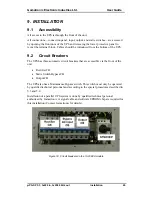
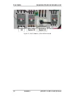
The UPS has three automatic circuit breakers that are accessible via the front of the
unit.
•
Rectifier CB
•
Static Switch Bypass CB
•
Output CB
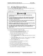
The UPS also has a Maintenance Bypass switch. This switch must only be operated
by qualified technical personnel and according to the special procedures described in
5.3 and 5.4.
Installation of a parallel UPS system is done by qualified technical personal
authorized by Gamatronic. A signal cable and software EPROM chip are required for
this installation (Contact Gamatronic for details).
Figure 18: Circuit breakers on the 10-20KVA models

