User Guide Gamatronic Electronic Industries Ltd.
µ
PS-SP 3:3, 3x220 in, 3x208 60 Hz out
Installation
52
9.5 Parallel
Start-Up
This section describes the start-up procedure for parallel UPSs. For a technical
description of the parallel scenario, please refer to section 3.1.1 on page 8.
9.5.1
Decentralized (2 UPSs only)
To start-up both UPSs, after successfully completing the installation procedure, and
connecting the cables to the rectifier input, ST.SW input, maintenance bypass output
and batteries, perform the following steps:
1.
Verify that all circuit breakers are turned off in both UPSs.
2.
Verify that both UPSs are connected to the same bypass source and with
the same phase sequence.
3.
Verify that the parallel communication cable is securely connected to the
D15 female connector labeled as PAR.COM. on both UPSs.
4.
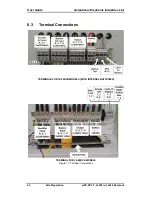
Make sure that the three PAR ST.SW bus terminals in both UPSs are
connected to each other in the correct order (1 to 1, 2 to 2 and 3 to 3). The
PAR. ST.SW terminals are located on the bottom of the UPS adjacent to
the other terminals.
5.
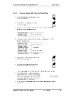
Start up one of the UPSs using the procedure described in “Turning On the
UPS for the First Time” on page 49.
6.
Start up the second UPS using the procedure described in “Turning On the
UPS for the First Time” on page 49.
7.
Leave the output circuit breakers of each UPS OFF.
8.
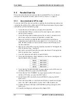
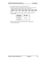
Verify that the following voltage differences exist between the Bypass AC
Input terminals of the two units:
V(R-R)
≤
500 mvAC
V(S-S)
≤
500 mvAC
V(T-T)
≤
500 mvAC
V(N-N)
≤
500 mvAC
9.
Verify that the “MASTER MODE” message appears on the LCD screen of
the Master UPS when you press the STAT button.
10.
Verify that the “SLAVE MODE” message appears on the LCD screen of
the Slave UPS when you press the STAT button.
11.
On the Master UPS, transfer the load to BYPASS by pressing the B/P
button twice.
12.
Check the status LEDs to verify that both UPSs have transferred to bypass
mode. The “B/P” LED should be red, the “INV” LED should be off.
13.
Transfer the Master UPS back to INVERTER mode by pressing the INV
button once.
14.
Turn ON the Output circuit breaker of the Master UPS.

