Directions For Use
3.
17
Initial
installation
After
successfully
connecting
your
DVD
recorder
to
the
T
V
set
and
other
additional
devices
as
described
in
the
previous
chapters,
this
chapter
will
show
you
how
to
start
the
initial
installation.
The
DVD
recorder
automatically
seeks
and
stores
all
available
T
V
channels.
Switching
on
additional
devices
If
you
have
connected
additional
devices
such
as
a
satellite
receiver
to
the
aerial
cable,
switch
them
on.
The
automatic
channel
search
will
recognise
it
and
save
it.
Please
observe
that
you
must
switch
on
a
"test
signal"
for
some
additional
devices.
No
aerial
connected
Even
if
you
only
want
to
use
the
DVD
recorder
to
play
back
or
have
only
connected
a
satellite
receiver,
you
must
still
complete
the
initial
installation.
This
is
necessary
so
that
the
basic
settings
are
stored
correctly.
Once
initial
installation
is
complete
you
can
use
the
DVD
recorder
as
normal.
1
Press
STANDBY-ON
m
on
the
front
of
the
DVD-recorder
P
'
PHILIPS
'and
then
'
IS
TV
ON?
'w
ill
appear
o
n
the
display.
P
If
the
connection
was
properly
made
and
your
TV
was
automatically
switched
to
the
programme
number
for
the
input
socket,
e.g.
'EXT',
'0',
'AV',
you
will
see
the
following
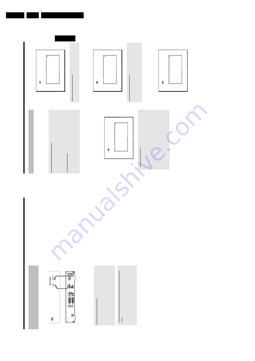
picture:
Virgin
mode
Menu
Language
English
Español
Français
Italiano
Deutsch
Press
OK
to
continue
a
My
screen
is
empty.
b
Depending
on
the
initialisation
procedure
it
can
take
some
time
before
the
picture
appears.
Please
press
no
button
in
the
meantime.
b
If
the
TV
set
does
not
automatically
switch
to
the
programme
number
of
the
input
socket,
select
the
corresponding
programme
number
on
your
TV
set
manually
(see
your
TV's
operating
instructions).
b
Check
that
the
scart
cable
is
connected
from
the
TV
set
to
the
EXT1
TO
TV-I/O
socket
on
the
DVD
recorder.
The
EXT2
AUX-I/O
socket
is
intended
only
for
additional
devices.
2
Select
the
desired
language
for
the
on-screen
menu
by
pressing
B
or
A
.
Virgin
mode
Menu
Language
English
Español
Français
Italiano
Deutsch
Press
OK
to
continue
What
is
an
on-screen
menu?
All
settings
and/or
functions
are
displayed
on
your
TV
screen
in
the
relevant
language.
3
Confirm
w
ith
OK
.
4
Select
the
desired
audio
language
using
B
or
A
.
Virgin
mode
Audio
Language
English
Español
Français
Português
Italiano
Press
OK
to
continue
What
is
an
audio
language?
The
DVD
will
play
the
sound
in
the
language
you
select,
provided
this
language
is
available
on
the
disc.
If
it
is
not
available
on
the
disc
the
first
language
on
the
DVD
will
be
used
instead.
The
DVD
Video
Disc
menu,
if
available,
will
also
be
displayed
in
the
language
you
select.
5
Confirm
w
ith
OK
.
6
Select
the
desired
language
for
the
subtitles
by
pressing
B
or
A
.
Virgin
mode
Subtitle
Language
English
Español
Français
Português
Italiano
Press
OK
to
continue
ENGLISH
Installation
16
Connecting
audio
devices
to
the
digital
audio
sockets
At
the
back
of
the
DVD
recorder
there
are
two
digital
audio
output
sockets
OPTICAL
OUT
for
an
optical
cable
and
COAX
OUT
for
a
coaxial
cable
(Cinch
cable).
These
can
be
used
to
connect
the
following:
•)
an
A/V
receiver
or
an
A/V
amplifier
w
ith
a
digital
multichannel
sound
decoder
•)
a
receiver
with
twochannel
digital
stereo
(PCM)
Digital
multi-channel
sound
Digital
multi-channel
sound
offers
the
best
possible
sound
quality.
You
will
need
a
multi-channel
A/V
receiver
or
amplifier
that
supports
at
least
one
of
the
audio
formats
of
the
DVD
recorder
(MPEG2
and
Dolby
Digital).
Consult
the
operating
instructions
for
your
receiver
to
find
out
which
audio
formats
it
supports.
a
All
I
can
hear
from
my
loudspeakers
is
a
loud
distorted
noise
b
The
receiver
is
not
compatible
with
the
digital
audio
format
of
the
DVD
recorder.
The
audio
format
of
the
DVD
disc
is
displayed
in
the
status
window
when
you
switch
to
another
language.
Playback
in
six-channel
digital
surround
sound
is
only
possible
if
the
receiver
has
a
digital
multi-channel
sound
decoder.
Connecting
additional
devices
Содержание DVDR730/0x
Страница 40: ...Mechanical Instructions EN 40 DVDR730 0x 4 Figure 4 14 Figure 4 15 5 5 6 7 ...
Страница 98: ...EN 98 DVDR730 0x 7 Circuit Diagrams and PWB Layouts Layout Analog Board Part 2 Bottom View 17025b_001 230204 ...
Страница 101: ...Circuit Diagrams and PWB Layouts EN 101 DVDR730 0x 7 Layout UP Sub Board Top View TR 06012_001 040203 ...
Страница 104: ...EN 104 DVDR730 0x 7 Circuit Diagrams and PWB Layouts Layout In Out Extension Board TR 06037_00 1 06020 3 ...
Страница 116: ...EN 116 DVDR730 0x 7 Circuit Diagrams and PWB Layouts ...
Страница 129: ...Circuit IC descriptions and list of abbreviations EN 129 DVDR730 0x 9 9 4 4 Video routing Figure 9 3 Video IO Nafta ...
Страница 135: ...Circuit IC descriptions and list of abbreviations EN 135 DVDR730 0x 9 Figure 9 9 ...
Страница 136: ...Circuit IC descriptions and list of abbreviations EN 136 DVDR730 0x 9 Figure 9 10 ...
Страница 140: ...Circuit IC descriptions and list of abbreviations EN 140 DVDR730 0x 9 IC7411 NJM2285 Analog Board Video Switch ...
Страница 150: ...Spare Parts List EN 150 DVDR730 0x 10 10 Spare Parts List 10 1 Exploded View of the Set Figure 10 1 TR 13012_001 220803 ...
Страница 151: ...Spare Parts List EN 151 DVDR730 0x 10 10 2 Exploded View of the Front Panel Complete Figure 10 2 TR 13013_001 220803 ...
Страница 152: ...Spare Parts List EN 152 DVDR730 0x 10 10 3 Exploded View of the Front without PWBs Figure 10 3 TR 13014_001 220803 ...


