SMART I/O User’s Manual
March 12, 1996
©1996 PEP Modular Computers GmbH
Page 1 - 12
Introduction
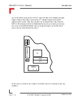
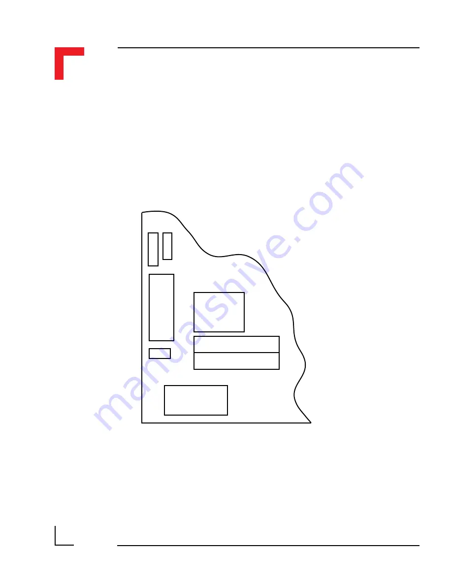
An on-board fuse protects the 24V DC input circuitry from damage through
higher voltages than those expected or AC voltages being inadvertently
applied to the system. This fuse, should it be assumed defect (the Power In
LED on the housing will not be illuminated), may be accessed by removing
the cover of the SMART-BASE and accessing the holder on the left-hand
side as shown in the illustration below.
In the event of a blown fuse, replace it with the same size and type as the one
installed.
D3
D4
C6
C7
C1
SCR2
1
2
3
R77
F1 0.60A M
Содержание Modular Computers RS232
Страница 2: ...This page was intentionally left blank ...
Страница 12: ...This page was intentionally left blank ...
Страница 18: ...SMART I O User s Manual March 12 1996 1996 PEP Modular Computers GmbH Page 1 6 Introduction ...
Страница 89: ...Digital Modules 08 Jan 98 SMART I O User s Manual Page 4 1 Manual ID 09901 Rev Index 0500 Digital Modules ...
Страница 92: ...This page was intentionally left blank ...
Страница 143: ...Digital Modules 08 Jan 98 SMART I O User s Manual Page 4 57 Manual ID 09901 Rev Index 0500 Figure 4 3 Solder Side ...
Страница 149: ...Digital Modules 08 Jan 98 SMART I O User s Manual Page 4 63 Manual ID 09901 Rev Index 0500 Figure 4 7 Connection ...


