SMART I/O User’s Manual
©1996 PEP Modular Computers GmbH
March 12, 1996
Page 1 - 17
Introduction
1
1.4.5 Battery Installation
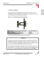
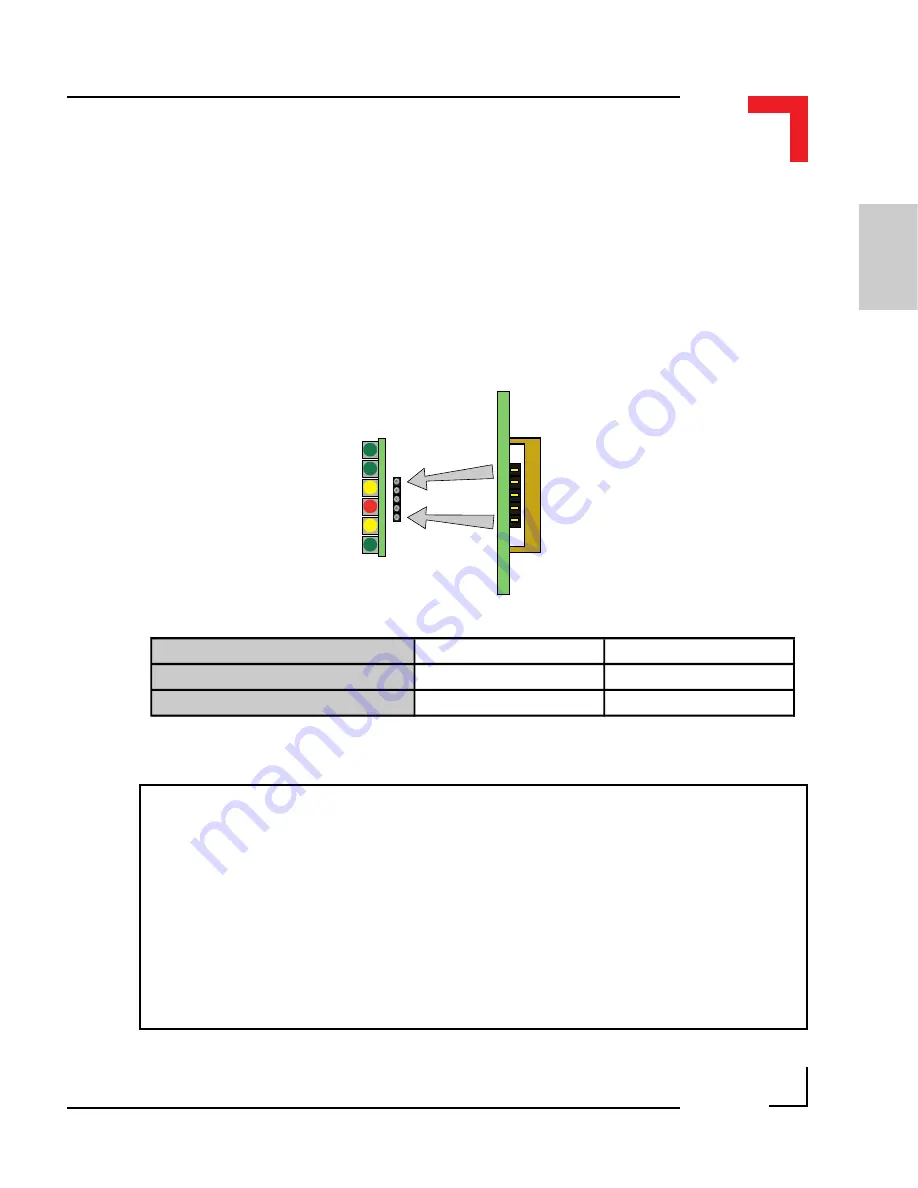
The battery piggyback SMPBBAT is fitted into the socket BU3 on the
SMART-BASE. It is important that the piggyback is inserted in the correct
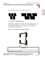
way. The figure below illustrates this procedure.
Figure 1.4.5.1: Battery Piggyback Installation
SMPBLED
BU3
Pin 1
Pin 5
SMPBBAT
Battery
WARNING!
Once fitted on the board, the battery should be on the right hand side of the
SMPBBAT piggyback. If the battery needs to be replaced, it must only be
done with a replacement SMPBBAT piggyback, the order number of which
is shown in the Ordering Information section of this manual.
The temperature on the battery must not 70
°
C, due to the risk of
battery damage! For SMART I/O modules with extended temperature ranges
of up to 85
°
C, a special lithium battery must be fitted to the SMPBBAT.
Battery Type
3V Lithium BR2032
3V Lithium CR14250
Battery Capacity
190mAh
850mAh
Typical Data Retention Time *140 Days
590 Days
* this is the time without the main power being applied
Содержание Modular Computers RS232
Страница 2: ...This page was intentionally left blank ...
Страница 12: ...This page was intentionally left blank ...
Страница 18: ...SMART I O User s Manual March 12 1996 1996 PEP Modular Computers GmbH Page 1 6 Introduction ...
Страница 89: ...Digital Modules 08 Jan 98 SMART I O User s Manual Page 4 1 Manual ID 09901 Rev Index 0500 Digital Modules ...
Страница 92: ...This page was intentionally left blank ...
Страница 143: ...Digital Modules 08 Jan 98 SMART I O User s Manual Page 4 57 Manual ID 09901 Rev Index 0500 Figure 4 3 Solder Side ...
Страница 149: ...Digital Modules 08 Jan 98 SMART I O User s Manual Page 4 63 Manual ID 09901 Rev Index 0500 Figure 4 7 Connection ...

