SMART I/O User’s Manual
©1996 PEP Modular Computers GmbH
October 01, 1996
Page 6 - 23
6
Chapter 6 Communications Modules
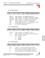
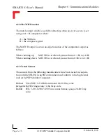
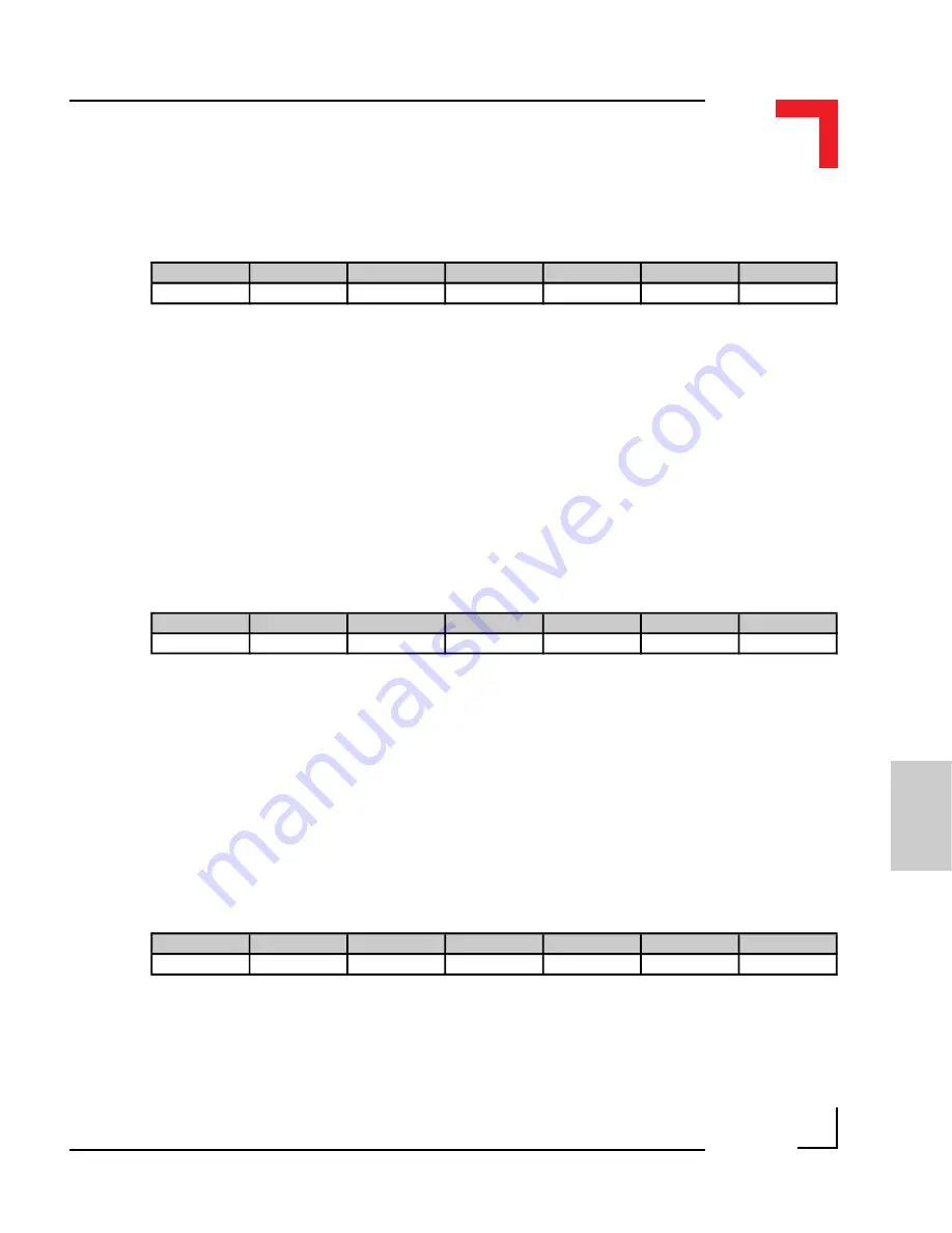
6.2.7.2 CTRL1 Register
ENIO-P
enable / disable (1 / 0) interrupt on parity error
ENI1-TC
enable / disable (1 / 0) interrupt on transmission complete
ENI2-EOR enable / disable (1 / 0) interrupt on end-of-range switch 1 / 2
ENI3-MH enable / disable (1 / 0) interrupt on comparison match
DIR
direction control (‘1’ activates the optocouplers)
SOT
start transmission control (‘1’ = set; single-shot-set by lib.)
AR
select automatic repeat mode (when set -> ‘1’)
RST
set / clear (1 / 0) Reset output
6.2.7.3 CTRL2 Register
FDL0-4
number of data bits, excluding parity, minus 1
P
enable / disable (1 / 0) use of parity (encoder dependent)
CF1-0
data transmission frequency:
0-0
62.5 kHz
1-0
125 kHz
0-1
250 kHz
1-1
500 kHz
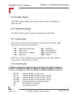
6.2.7.4 CTRL3 Register
CM
A logical ‘1’ clears the MATCH output and LED
DT
data type (0:Gray, 1:Binary) according to encoder type
If ‘0’ is set, the result in the data register is binary.
PT
parity type (0:Odd, 1:Even) according to encoder type.
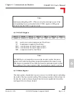
CTRL1-7
CTRL1-6
CTRL1-5
CTRL1-4
CTRL1-3
CTRL1-2
CTRL1-1
RST
AR
SOT
DIR
EN13-MH
EN12-EOR
ENI1-TC
CTRL2-7
CTRL2-6
CTRL2-5
CTRL2-4
CTRL2-3
CTRL2-2
CTRL2-1
CF1
CF0
P
FDL4
FDL3
FDL2
FDL1
CTRL3-7
CTRL3-6
CTRL3-5
CTRL3-4
CTRL3-3
CTRL3-2
CTRL3-1
unused
unused
unused
unused
unused
PT
DT
Содержание Modular Computers RS232
Страница 2: ...This page was intentionally left blank ...
Страница 12: ...This page was intentionally left blank ...
Страница 18: ...SMART I O User s Manual March 12 1996 1996 PEP Modular Computers GmbH Page 1 6 Introduction ...
Страница 89: ...Digital Modules 08 Jan 98 SMART I O User s Manual Page 4 1 Manual ID 09901 Rev Index 0500 Digital Modules ...
Страница 92: ...This page was intentionally left blank ...
Страница 143: ...Digital Modules 08 Jan 98 SMART I O User s Manual Page 4 57 Manual ID 09901 Rev Index 0500 Figure 4 3 Solder Side ...
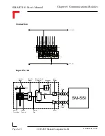
Страница 149: ...Digital Modules 08 Jan 98 SMART I O User s Manual Page 4 63 Manual ID 09901 Rev Index 0500 Figure 4 7 Connection ...

