SMART I/O User’s Manual
March 12, 1996
©1996 PEP Modular Computers GmbH
Page 1 - 24
Introduction
In order to verify that the hardware and software have been correctly setup,
the following procedure should be followed.
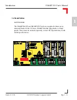
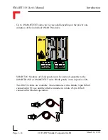
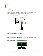
• Connect the D-Sub connector end of the terminal cable to the chosen
COM port of the computer. The other end, with the telephone type
connector should be pushed into place in the RS232-port of the
SMART I/O base (see figure 1.4.3.1)
• With the power supply turned OFF, connect the power plug to SCR-2
on the SMART base.
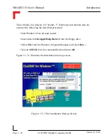
• Start the
ISA-Terminal
program.
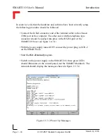
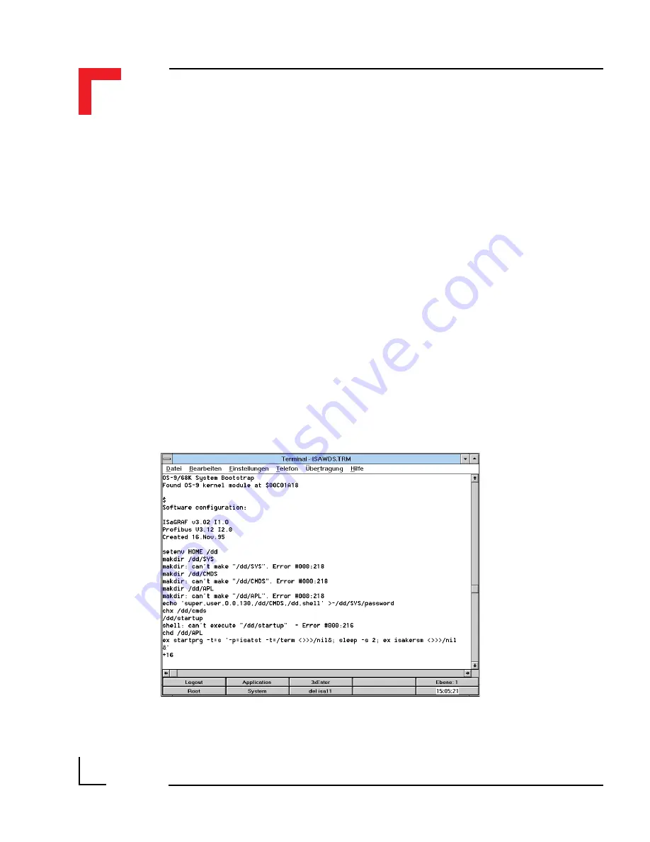
• Switch on the power supply to the SMART I/O; three green LEDs
should illuminate on the control panel (not the SMART Modules!). The
terminal should display the messages shown in figure 1.5.3.2.
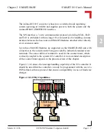
Figure 1.5.3.2 Power Up Messages
Содержание Modular Computers RS232
Страница 2: ...This page was intentionally left blank ...
Страница 12: ...This page was intentionally left blank ...
Страница 18: ...SMART I O User s Manual March 12 1996 1996 PEP Modular Computers GmbH Page 1 6 Introduction ...
Страница 89: ...Digital Modules 08 Jan 98 SMART I O User s Manual Page 4 1 Manual ID 09901 Rev Index 0500 Digital Modules ...
Страница 92: ...This page was intentionally left blank ...
Страница 143: ...Digital Modules 08 Jan 98 SMART I O User s Manual Page 4 57 Manual ID 09901 Rev Index 0500 Figure 4 3 Solder Side ...
Страница 149: ...Digital Modules 08 Jan 98 SMART I O User s Manual Page 4 63 Manual ID 09901 Rev Index 0500 Figure 4 7 Connection ...

