© Panasonic Industrial Devices SUNX Co., Ltd. 2016
69
Connection of this Device and a PC
5-5 Connection of this Device and a PC
5-5-1 Connection to “Monitor Mode”
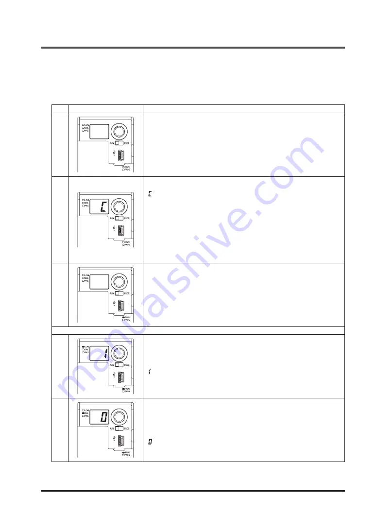
To recognize this device by connecting it to a PC, perform the following procedure:
Step Status of indicators and switches
Description
1
Power: OFF
Mode selector switch: RUN side
With the internal power supply and external power supply turned OFF, con-
nect this device with a PC via the USB cable.
2
Turn ON the power supply.
“ ” is displayed in the 7-segment indicator (red).
All the other indicators turn OFF.
*: If an error message, for example, “Your USB device is not recognized,” is
displayed in the PC, plug and unplug the USB connector, or turn ON the
power supply again. This prevents displaying the message.
Press the rotary switch.
*: If the connection is made for the first time, press the rotary switch after the
completion of USB driver installation.
3
The device enters “Monitor mode.”
The operation indicator (green) lights up.
In “Monitor mode,” the software tool is used to read data from and monitor
this device.
“Monitor mode” prevents writing data into this device.
When writing data into this device, refer to Procedure “
”.
4
Press the rotary switch.
The logic No. currently set is displayed in the 7-segment indicator (red).
Logic selection indicator (orange) lights up.
“
: Overall stop control” is set at factory.
5
Rotate the rotary switch.
The currently set No. for OFF delay time is displayed in the 7-segment indi-
cator (red).
Delay selection indicator (orange) lights up.
“
: 0 sec.” is set at factory.
Rotating the rotary switch returns to No.1.
The procedure above is enabled either before or after the activation of the software tool that is
described in the next section.


