Screen Menus and Definitions
A-2
Logon Screens
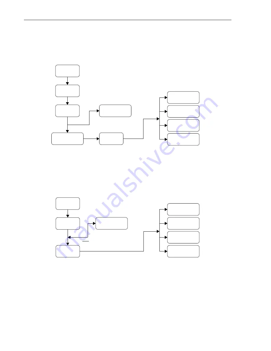
Figure A-1 shows the logon sequence for accessing a PG-Flex system through an FAU-728 List 2
or a PGTC interface card. Refer to “FPI-729 Main Menu and Configuration Screens” on page 5.
Figure A-1. Logon Sequence Through an Alarm Unit of PGTC Interface
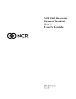
Figure A-2 shows the logon sequence for accessing a PG-Flex system through a line unit. Refer to
“Main Menu Screen” on page 7.
Figure A-2. Logon Sequence Through a Line Unit
The following pages contain samples of logon screens for the PG-Flex system.
Status
Logon
FPI Main
Connect to
System
Setup
Maintenance
Inventory
Connect to COT
(COT 1 through 4)
Configuration
Main
Status
Logon
Main Menu
Connect to
System
Setup
Maintenance
Inventory
System Time
1st time
logon only
Содержание PG-Flex
Страница 10: ...PG Flex System Overview 2 Figure 1 Typical PG Flex Configuration 23 Shelf shown ...
Страница 24: ...PG Flex System Overview 16 ...
Страница 44: ...Installing PG Flex System Hardware 36 Figure 16 Line Unit and Channel Unit Installation Locations ...
Страница 52: ...Installing PG Flex System Hardware 44 Figure 21 Connecting the Metallic Bypass Pair ...
Страница 62: ...Installing PG Flex System Hardware 54 ...
Страница 66: ...Terminal Management 58 Figure 28 Connecting an ASCII Terminal to a Line Unit ...
Страница 104: ...Performance Monitoring 96 ...
Страница 120: ...Troubleshooting 112 ...
Страница 158: ...Screen Menus and Definitions A 36 ...
Страница 162: ...Acronyms and Glossary Glossary 4 ...
Страница 167: ......
Страница 168: ......


