Connecting the Rear Power Cords and Data Cables
135
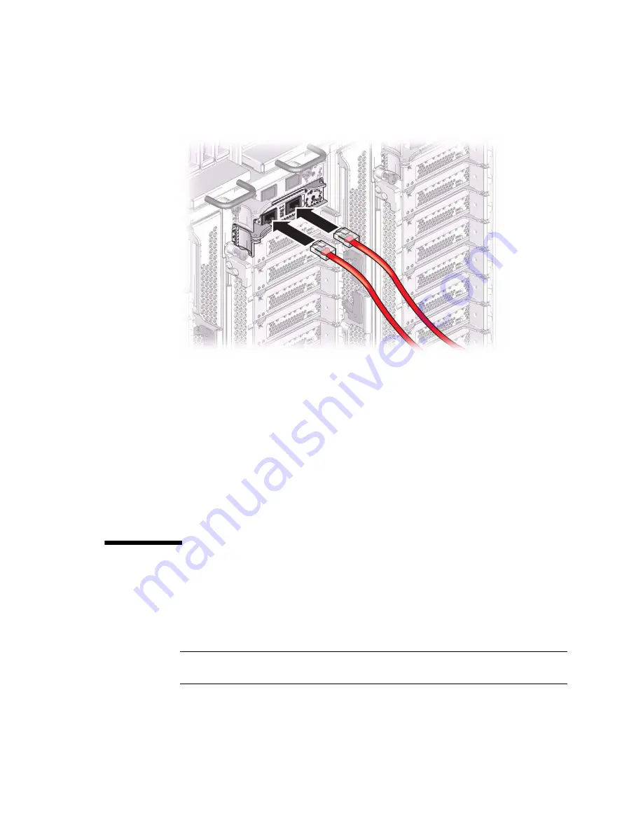
3. Connect additional Category 6A (or better) cables from your network switch or
hub to the remaining 10-GbE ports on other EMS modules, as needed for your
server configuration.
4. Secure the network cables to the server.
See
“Managing Data Cables” on page 136
Related Information
■
“PDomain Cables and Network Addresses” on page 65
■
“Maximum Cable Connections” on page 121
■
“Managing Data Cables” on page 136
▼
Connect Other Data Cables
1. If your server configuration includes optional PCIe cards, connect the
appropriate I/O cables to their connectors.
Refer to the PCIe card documentation for specific instructions.
Note –
For instructions on installing optional PCIe cards using the PCIe hot-plug
carrier, refer to the
Server Service
, servicing I/O cards.
Содержание sparc M5-32
Страница 1: ...SPARC M5 32 and SPARC M6 32 Servers Installation Guide Part No E41215 05 December 2014 ...
Страница 8: ...viii SPARC M5 32 and SPARC M6 32 Servers Installation Guide December 2014 ...
Страница 16: ...6 SPARC M5 32 and SPARC M6 32 Servers Installation Guide December 2014 Front Components ...
Страница 18: ...8 SPARC M5 32 and SPARC M6 32 Servers Installation Guide December 2014 Rear Components ...
Страница 21: ...Understanding the Server 11 FIGURE DCU Locations Rear of Server ...
Страница 43: ...Preparing the Site 33 FIGURE 4 Wire Power Cord AC Plug 460P9W Figure Legend 1 L1 2 L2 3 L3 4 Ground ...
Страница 51: ...Preparing the Site 41 ...
Страница 82: ...72 SPARC M5 32 and SPARC M6 32 Servers Installation Guide December 2014 ...
Страница 106: ...96 SPARC M5 32 and SPARC M6 32 Servers Installation Guide December 2014 ...
Страница 182: ...172 SPARC M5 32 and SPARC M6 32 Servers Installation Guide December 2014 ...


