FiberPoint MEM Installation
3-1
Form 361015-0001A
FiberPoint Structured Wiring Enclosure Installation Guide
3
FiberPoint MEM Installation
Form 361015-0001A
FiberPoint Structured Wiring Enclosure Installation Guide
O
VERVIEW
This chapter provides installation instructions for installing
the FiberPoint MEM into the Structured Wiring Enclosure
(SWE) and connecting it to the FTTH network. Final set-up
and testing is also included.
I
NSTALLATION
A
SSUMPTIONS
For purposes of this manual, it is assumed that the
FiberPoint MEM is being mounted in a SWE of suitable
size to house all telecommunications devices being
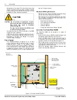
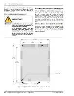
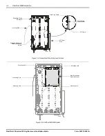
implemented. See ‘Figure 3-1: Structured Wiring Enclosure
Access Points’ for dimensioning information.
2031
NOTICE
NOTICE: A Class I laser product is used in this equip-
ment. Use an optical power meter to identify
active fibers. Never assume laser power is
turned off or that the fiber is disconnected
at the other end.
A protective cap or hood must be placed
over any radiating bulkhead receptacle or
optical fiber connector.
1118
CAUTION
CAUTION: Use of controls, adjustments or procedures
other than those specified herein may result
in hazardous radiation exposure.
T
IPS
ON
H
ANDLING
F
IBER
O
PTIC
C
ABLE
Follow these tips when handling fiber optic cable for trouble
free performance.
•
Keep fiber optic cables and splicing equipment clean
at all times. Use manufacturer approved solvents and
cleaning applicators. For more detailed information on
Fiber Optic Cable installation and maintenance, see
Chapter 4, ‘Fiber Splicing Techniques’.
•
Take care to use the proper connectors for the
application. Mismatching connectors or the use of the
wrong type of connector can result in the loss of
optical power and damage to the connectors.
•
When routing optic fibers, be careful to avoid bending
the fibers beyond the manufacturer recommended
bend radius. Exceeding the 1” (2.54 cm) bend radius
can cause excess attenuation and possibly break the
fiber. The use of vendor specified radius clips is highly
recommended. Refer to the list of vendors inside the
front cover for information.
•
Verify all optical power levels before connections are
made. If excessive loss is noted, the use of an optical
time domain reflectometer (OTDR) may be required.
Optical power levels are a function of the incoming
power, and cumulative losses due to distance, splits/
merges and/or splices in the PON. For assistance in
determining expected optical levels, refer to Form
361003-0001 FiberPath 500 System Installation Guide
(HeadEnd) or Form 367001-0001 FiberPath 500
System Design Guidelines. These two manuals
include a GPON calculator which allows you to enter
your specific system parameters and determine
whether you have sufficient theoretical budget to
configure your network.
I
NSTALLATION
C
ONSIDERATIONS
NOTE: It is assumed that the FiberPoint MEM has
been unpacked and checked against the pack-
ing list to ensure all parts are present prior to
beginning the installation.
WARNING
1106
WARNING: It is critical that you maintain the
proper airflow around the FiberPoint
MEM unit in it’s final mounted
location.
The SWE can be flush mounted or
recessed to an interior wall provided
proper airflow exists behind the cover
and that temperatures do not exceed
recommended levels (See Reference
Section in the back of this manual for
specific information).
Do not mount the MEM or the enclo-
sure near a furnace or hot air duct.
Inside temperature must not exceed
65° C (149° F).
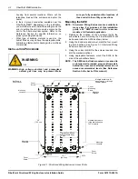
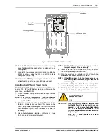
Various access points are available within the housing
which may or may not be used. Prior to mounting the
FiberPoint unit, you need to consider the following
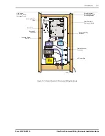
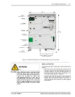
variables (See ‘Figure 2-2:FiberPoint Main Electronics
Module Mounting and Access Points’):
•
Will CATV services be ordered? The output of the
CATV bulkhead fitting may exit the FiberPoint

