3-10
FiberPoint MEM Installation
FiberPoint Structured Wiring Enclosure Installation Guide
Form 361015-0001A
F
INAL
S
ET
-
UP
AND
T
ESTING
1.
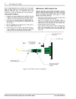
Plug in the UPS to the home premises power source.
Both the green AC Power and DC Power indicators on
the UPS should light. (See ‘Figure 3-6: UPS and
Power Supply Connections’.)
2.
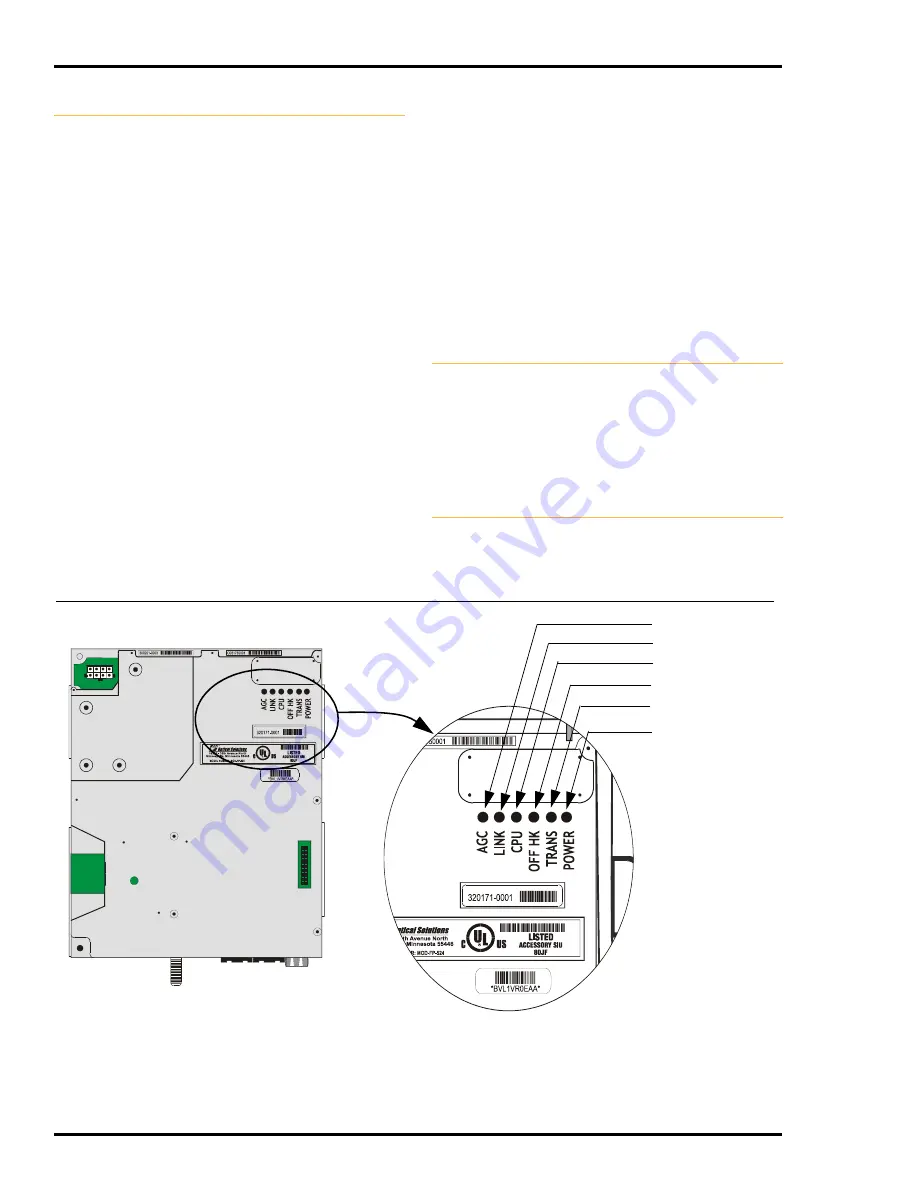
Return to the FiberPoint MEM and view the LEDs.
3.
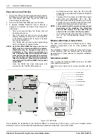
A properly installed FiberPoint will go through a
sequence of operation as follows (See ‘Figure 3-9:
LED Status’):
•
After a two second delay, the Power LED will
illuminate and stay on.
•
The CPU light will also come on and begin
blinking indicating the processor in the FiberPoint
is functioning properly and is ready to transmit
and receive information.
•
The TRANS LED will come on and begin blinking
as the unit begins its ranging function.
NOTE: Each FiberPoint MEM that comes on line in a
PON must be provisioned within the system.
FiberPoints may be pre-provisioned prior to
installation or they may be provisioned on
site. In the latter case, the installing technician
must call the HeadEnd operator for provision-
ing. The testing scenario listed here assumes
that all services are present, pre-provisioned
and waiting for FiberPoints MEM’s to be added
to the PON.
•
Once the MEM has been discovered and
provisioned, the TRANS LED will stay on.
•
As Telephone services begin, the OFF HK LED
will light when any telephone attached to the MEM
is Off Hook.
•
Typically, after 10 seconds, the LEDS (left to right)
will be ON - ON - BLINKING - OFF - ON - ON.
Once this status has been achieved, you can be
sure that the unit is installed correctly and will be
capable of providing services as necessary.
NOTE: It is assumed that all services are present and
functioning at the HeadEnd. For FiberPoint
502 and 504 models, the first LED will not
come on since no video circuitry is present.
•
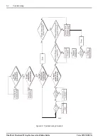
If you cannot achieve this sequence of operation,
turn to the Troubleshooting chapter of this
manual.
M
AKING
A
DDITIONAL
C
ONNECTIONS
The SWE will normally have sufficient space to house
additional components, such as video splitters, data
routers, etc.
The installation of these components is beyond the scope
of this document and you should refer to the specific
manufacturer’s of these devices for complete installation
instructions.
S
ECURING
THE
U
NIT
Prior to putting the FiberPoint MEM into service, the SWE
cover needs to be secured.
Attach the cover using the (4) screws provided with the
SWE.
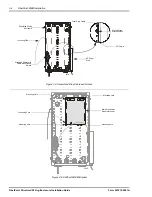
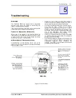
Figure 3-9: LED Status
This completes the installation of the FiberPoint MEM. For provisioning of this device, or for more complete system
information, refer to the FiberPath 500 HeadEnd Bay Installation Instructions, Form 361003-0001.
2914
Hook Status
Video Signal
Ethernet Link
CPU Status
Transport Status
Power Status
3487

