background image

R - 2

Reference

FiberPoint Structured Wiring Enclosure Installation Guide

Form 361015-0001A

spikes that are present during electrical storms and static
buildup on power utility lines have been known to cause a
great deal of damage to electronic equipment. When the
voltage potentials reach sufficient amplitude, flashovers
take place. In most cases, damage is caused by the super
heating present during the flashover. The high voltage
potentials that are induced into AC utility conductors and
communications cables during electrical storms are of a
wavelength that approaches the RF spectrum. To be
effective in the discharging of induced RF energy,
grounding conductors must provide a low impedance path
to earth. Keeping conductors as short as possible and
using the most direct path, free of sharp bends, will help to
lower the impedance of the ground circuit. 

NOTE: Grounding conductors should never be

placed inside a metallic conduit unless
bonded at both ends of the conduit so that the
conduit itself becomes the conductor.

Testing the Earth Electrode

The earth electrode is the bonding or connection point to
the earth. The most common earth electrodes are ground
rods, metallic cold water pipes, underground grids and
water wells that use steel pipe. The ability of a grounding
system to safely dissipate unwanted or harmful potentials
into the earth, depends on the total resistance of the
electrode, the resistance between the conducting surface
of the electrode and the conducting surface of the soil that
it is in. The conductivity of the earth near and around the
grounding system depends on the chemical makeup and
ambient moisture content of the soil.

The testing of an electrode measures the effectiveness of
the earth electrode to provide electrical contact with the

earth. The lower that the resistance to the earth is, the
more effective the ground system will be in dissipating
energy safely.

To understand the testing procedure of an earth electrode,
one must first understand some of the principles of ground
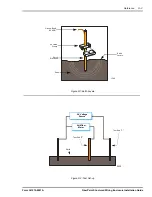
conductivity. The earth acts like it is made up of layers that
bear a resemblance to an onion. Like an onion, the earth is
made up of expanding sections or peels (layers). An
electrode placed into the earth radiates current in all
directions along the surface of each of these layers. See
‘Figure R-1:Earth Layers’. As the layers extend outward
from the electrode, their surface area becomes larger
compared to the layers nearest the electrode. The
resistance of each of layer decreases in relation to the
amount of surface area. From a starting point next to the
earth electrode, the resistance measurement to earth will
increase with distance. The amount of resistance increase
due to distance will taper off at some point. As the distance
from the electrode increases, the resistance to earth does
not increase. As more measurements are taken beyond
this point, the amount of resistance to earth will start to
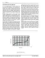
increase again. See ‘Figure R-2: Test Set-up’. The test
setup uses an Earth Resistance Megger to determine the
resistance of an earth electrode. Grounding system tests
are commonly made with a “full of potential” test set. Within
the test set is a AC current source, a voltage meter and a
number of test terminal binding posts. The AC voltmeter
inside of the test set reads out directly in Ohms of
resistance. By reading the voltage drop across a current
path and applying Ohms Law, the total resistance of the
ground plus the surface resistance of the earth electrode to
the surrounding ground can be measured.

Содержание FiberPoint

Страница 1: ...INSTALLATION GUIDE FiberPoint Structured Wiring Enclosure...

Страница 2: ...2675 www corning com cablesystems For additional information on exit fittings riser pipes contact McMaster Carr Supply Company P O Box 4355 Chicago IL 60680 4355 Phone 630 833 0300 Fax 630 834 9427 N...

Страница 3: ...Class x Hazardous Materials xi Applicable Standards xi Laser Standards xi Glossary of Terms xi Publication Version xiv Revision History xiv Introduction Overview 1 1 FiberPath 500 System 1 1 FTTH Netw...

Страница 4: ...inal Set up and Testing 3 10 Making Additional Connections 3 10 Securing the Unit 3 10 Fiber Splicing Techniques Overview 4 1 Fiber Splicing Techniques 4 1 Jacket Preparation 4 1 Fiber Preparation 4 1...

Страница 5: ...oss R 11 Laser Power Calculation R 11 PON Design Guidelines R 11 Nominal Installations R 11 Voice Data Only System GPON R 11 Voice Data RF Video System VPON R 12 Restricted Installations R 12 If RF Tr...

Страница 6: ...rPoint Electronics Module Mounting and Access Points 2 2 Figure 3 1 Structured Wiring Enclosure Access Points 3 3 Figure 3 2 Ground Shield Assembly 3 3 Figure 3 3 Assembled Drop Cable and Ground 3 5 F...

Страница 7: ...ctured Wiring Enclosure Installation Guide List of Tables FiberPoint Structured Wiring Enclosure Installation Guide Form 361015 0001A Table Nbr Description Page Number Table 1 1 FiberPoint MEM Compone...

Страница 8: ...viii List of Tables FiberPoint Structured Wiring Enclosure Installation Guide Form 361015 0001A This page intentionally left blank...

Страница 9: ...may happen if the hazard is not avoided There are four types of safety messages Notice Warning Caution and Important The messages are flagged with a triangular safety icon Notice Message The notice m...

Страница 10: ...tenance The Class 1 laser used in the GPON card and FiberPoint unit are the least invasive as compared to higher powered optical laser transmitters The Notice label will look similar to this AGENCY LI...

Страница 11: ...e failure APC Angled Polished Connector An optical fiber that is cut at an angle and then polished at the end This type of end connector has less reflectance than a straight cut ultra polished connect...

Страница 12: ...n an ESF multi frame It is used to pass performance messages according to the ANSI T1 403 standard and can be used for proprietary messaging between network devices FIBERPOINT This is the generic name...

Страница 13: ...red to as the Plain Old Telephone Service POTS RDT Remote Digital terminal refers to the portion of the DLC responsible for interfacing to the LDS RF Radio Frequency SAR Segmentation and Re assembly r...

Страница 14: ...erPoint Structured Wiring Enclosure Installation Guide Form 361015 0001A Revision History The following revisions have been made to this publication Version Date Reason for Change Revision A 11 19 04...

Страница 15: ...d Wiring Enclosure SWE Telephones may be connected remotely up to 500 feet from the subscribers home The 500 feet off premise extension capability allows for remote telephone or other accessory locati...

Страница 16: ...rea near an AC power source Structured Wiring Enclosure SWE s are a new class of residential enclosures being used mostly in new housing developments SWE s allows for a central wiring distribution pan...

Страница 17: ...FiberPoint Main Electronics Module FiberPoint Main Electronics Module Mounting Bracket Structured Wiring Enclosure Patch Panel Data Hub Switch Video Splitter UPS w Battery Back up Not Shown Structure...

Страница 18: ...1 4 Introduction FiberPoint Structured Wiring Enclosure Installation Guide Form 361015 0001A This page intentionally left blank...

Страница 19: ...ng cables or wires and where they can most easily be routed See Figure 2 1 FiberPoint Main Electronics Module Mounting Bracket WARNING 1106 WARNING It is critical that you maintain the proper airflow...

Страница 20: ...in Electronics Module is mounted outside the premises the National Electrical Code NEC the Rural Electric Association REA and state local codes require that the FiberPoint Electronics Module be proper...

Страница 21: ...an at all times Use manufacturer approved solvents and cleaning applicators For more detailed information on Fiber Optic Cable installation and maintenance See Fiber Splicing Techniques in Chapter 4 T...

Страница 22: ...uate airflow WHAT S NEEDED FOR INSTALLATION Every installation needs the following components for a successful installation NOTE Check the contents of each box carefully as you receive it Components m...

Страница 23: ...S In addition to the above items earth grounding is essential for proper operation The following grounding supplies may also be needed 1 Sheath bonding clamp for composite cables incorporating a metal...

Страница 24: ...2 6 Pre Installation Requirements FiberPoint Structured Wiring Enclosure Installation Guide Form 361015 0001A This page intentionally left blank...

Страница 25: ...e fibers beyond the manufacturer recommended bend radius Exceeding the 1 2 54 cm bend radius can cause excess attenuation and possibly break the fiber The use of vendor specified radius clips is highl...

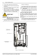
Страница 26: ...y sizes For purposes of this installation guide a 30 SWE is used in order to accom modate a full featured application 1 Determine the location of the enclosure inside the subscribers home Normally the...

Страница 27: ...upper right hand corner of the SWE 1 Locate the MEM Mounting Bracket 2 Using the bracket as a template mark the location of the four mounting holes with the bracket placed against the SWE See See Figu...

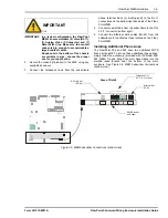
Страница 28: ...led Drop Cable and Ground Figure 3 4 SWE with MEM Bracket Wrapped Composite Cable with Ground Shield Ground Strap Attaches Here From Drop Cable AC Plug in AC Power Strip Incoming Fiber 3478 Structured...

Страница 29: ...g as a template to mark the hole locations Again ensure that the screws are not too long 3 Using the keyholes as a template drill holes for 2 two 8 32 pan head screws not provided NOTE Certain UPS man...

Страница 30: ...ry be sure to handle it gently Avoid tipping the battery on its side Check that the battery is free from cracks fractures and leakage Do not apply organic solvents such as paint thinner gasoline keros...

Страница 31: ...is turned off or that the fiber is disconnected at the other end A protective cap or hood must be placed over any radiating bulkhead receptacle or optical fiber connector Use of controls or adjustmen...

Страница 32: ...The GPON fiber must have no less than 25 dB of power 7 Plug in the green SC APC connector into the board as shown Make sure the connector is seated and secure NOTE Make sure the fiber end is clean an...

Страница 33: ...o the RJ 11 connections on the bottom right hand side of the Fiber Point MEM 4 Connect coaxial cable from the subscribers to the RG 59 F connector bottom right 5 Connect the Ethernet data cables RJ 45...

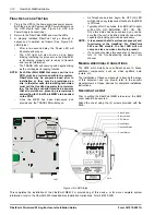
Страница 34: ...oned the TRANS LED will stay on As Telephone services begin the OFF HK LED will light when any telephone attached to the MEM is Off Hook Typically after 10 seconds the LEDS left to right will be ON ON...

Страница 35: ...of as little as 2 from perpendicular should be considered unacceptable The end finish should have a smooth mirror like finish free of blemishes hackles lips and burrs Ends should be prepared using th...

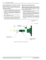
Страница 36: ...ith a dust cap to prevent contamination HANDLING OF APC CONNECTORS Although ruggedly constructed fiber connectors need to be handled with care when inserting the SC APC connector into the FiberPoint M...

Страница 37: ...ill result in a loss of service to a cluster of subscribers not just one or two Conversely communications problems that affect only one or two subscribers most always involve troubleshooting at the ME...

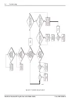
Страница 38: ...5 2 Troubleshooting FiberPoint Structured Wiring Enclosure Installation Guide Form 361015 0001A Figure 5 2 Troubleshooting Flowchart 2932...

Страница 39: ...Extreme care must be taken when attaching the ground connectors to the utility earth ground rod If the ground is interrupted or disturbed in any way an unsafe condition will exist Internal Mount Grou...

Страница 40: ...e testing of an electrode measures the effectiveness of the earth electrode to provide electrical contact with the earth The lower that the resistance to the earth is the more effective the ground sys...

Страница 41: ...oint Structured Wiring Enclosure Installation Guide Figure R 1 Earth Layers Figure R 2 Test Set up Ground Bond 6 AWG UL Listed Clamp Earth Layers Earth Earth Electrode 1399 AC Voltage Source Volt Ohm...

Страница 42: ...er of points that are along a line between the outer electrodes Each time the test probe is placed into the ground a resistance reading is taken and recorded A simple resistance curve is then plotted...

Страница 43: ...15 watts GPON module Power Max Watt Draw 4 ports enabled 38 watts Optical Power Tx Power Out Minimum 1 dBm Tx Power Out Maximum 4 dBm Rx Window 27 to 14 dBm Interfaces Data Interface 1 RJ45 Fiber Inte...

Страница 44: ...mber of Fiber Outputs 2 RF Interface 75 Ohm F connector RG 59 Fiber Interface SC APC See Specification number 600441 0001 for details Environmental Operating Temp 0 to 50 C 32 to 122 F Storage Temp 40...

Страница 45: ...avelength Maximum 1500 nm Signal Strength Minimum 25 dBm Signal Strength Maximum 3 dBm Voice Data PON Optical Output Wavelength Nominal 1310 nm Wavelength Minimum 1260 nm Wavelength Maximum 1360 nm Op...

Страница 46: ...502 Model 504 Model 522 Model 524 Model 560 Height 16 40 6cm 16 40 6cm 16 40 6cm 16 40 6cm 20 50 8 cm Width 12 30 5cm 12 30 5cm 12 30 5cm 12 30 5cm 16 2 41cm Depth 4 5 11 4cm 4 5 11 4cm 4 5 11 4cm 4 5...

Страница 47: ...budget since 1550 nm transmissions provide less loss as compared to 1310 and 1490nm transmissions Maximum PON Loss The FiberPoint Transmit Power and the Receive window of the GPON card are the main fa...

Страница 48: ...acteristic Value Type Level Tolerance Optical Input Power 3 8 OMI Minimum 5 dBm Optical Input Power 3 8 OMI Maximum 2 dBm Planning for Worst Case The VPON system is a 1550nm transmission The 1550 nomi...

Страница 49: ...ne 1X8 splitter is somewhere in the PON then enter quantity of 1 If the total length of fiber used to reach a home is 8km then enter quantity of 8 for fiber length NOTE PON loss in the upstream direct...

Страница 50: ...uppression or 8 km for 18 dBm SBS suppression or Launch video signal at SBS limit and lower maximum PON loss accordingly EDFA configuration does not support 20 0 5 dBm output power Launch at lower EDF...

Страница 51: ...7 25 0 00 0 0000 0 45 Splitter 1X8 connectorized 0 ea 10 38 0 00 0 0000 0 63 10 38 0 00 0 0000 0 63 Splitter 1X16 connectorized 1 ea 14 10 14 10 0 0900 0 90 14 10 14 10 0 0900 0 90 Splitter 1X32 conn...

Страница 52: ...r 1X32 connectorized 0 ea 17 45 0 00 0 0000 1 25 Fiber Length mi 10 mi 0 40 4 02 0 0072 0 08 Connectors APC 2 ea 0 25 0 50 0 0089 0 20 Splices 5 ea 0 05 0 25 0 0002 0 02 FiberPoint Connector 1 ea 0 40...

Страница 53: ...ng Enclosure Installation Guide Figure R 6 EDFA VPON Distribution 6 Mile PON Typical Distribution 512 Subscribers Served 256 Subs 20 equal ports of 20 dBm EDFA 1 EDFA 2 1550 nm 1550 nm 256 Subs 1550n...

Страница 54: ...ide Form 361015 0001A Figure R 7 Cascaded EDFA VPON Distribution EDFA 1 20 equal ports of 20 dBm EDFA 2 20 Splitters per EDFA 32 EDFA s 128 Ports Maximum Distribution 819 200 Subscribers Served 1550nm...

Страница 55: ...3 0 52 0 51 2 50 6 50 0 58 0 55 0 53 3 52 0 51 0 50 2 49 6 49 0 57 0 54 0 52 3 51 0 50 0 49 2 48 6 48 0 56 0 53 0 51 3 50 0 49 0 48 2 47 6 47 0 35 0 40 0 45 0 50 0 55 0 60 0 7 0 dBm Optical Input 6 0...

Страница 56: ...R 18 Reference FiberPoint Structured Wiring Enclosure Installation Guide Form 361015 0001A...

Отзывы: