


Fiber Splicing Techniques
4-1
Form 361015-0001A
FiberPoint Structured Wiring Enclosure Installation Guide
4
Fiber Splicing Techniques
Form 361015-0001A
FiberPoint Structured Wiring Enclosure Installation Guide
O
VERVIEW
In order to minimize optical link budget losses, it is
recommended that all fiber splices be completed with the
utmost care.
Following the suggestions below will provide you the basic
building blocks for properly fused splices.
F
IBER
S
PLICING
T
ECHNIQUES
1118
IMPORTANT
IMPORTANT: Optical Solutions, Inc. strongly
suggests that all fiber splices be fusion
splices. Purchase of a good quality
fusion splicer is highly recommended.
2031
NOTICE
NOTICE: A Class I laser product is used in this equip-
ment. Use an optical power meter to identify
active fibers. Never assume laser power is
turned off or that the fiber is disconnected
at either end.
A protective cap or hood must be placed
over any radiating bulkhead receptacle or
optical fiber connector.
WARNING
1106
WARNING: Only authorized service personnel should
attempt to repair this equipment. All prob-
lem discovery and repair procedures are
detailed to allow only subassembly/module
level repair. Due to the complexity of
design, no one should attempt to make
repairs at the component level or make
modifications to any circuit board.
Improper repairs can create a safety haz-
ard.
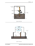
Jacket Preparation
Remove the jacket, buffer tubes and strength member
using a wire stripper or cutting pliers. The plastic buffer
coating should be removed with a high quality wire stripper.
Fiber Preparation
Proper preparation of the fiber end face is critical to any
fiber optic connection. Perpendicularity and end finish must
be within allowable tolerances in order to minimize signal
loss at these connections. A divergence of as little as 2°
from perpendicular should be considered unacceptable.
The end finish should have a smooth, mirror-like finish free
of blemishes, hackles, lips and burrs.
Ends should be prepared using the scribe and break
method. Holding the fiber under slight pressure, run the
cutting tool across the stationary fiber at perpendicular.
Properly done, the cleave produces a perpendicular,
mirror-like finish without hackles or lips. If major flaws are
noticed, the process must be repeated. Inspect the fiber
end under a microscope to ensure proper finish.
NOTE: Small scratches on the face or small pits on
the outside rim of the cladding are common
and should be considered acceptable. Fusion
splicer readings and experience more than
anything will determine the definition of
“small”.
Prior to putting the fiber ends into the fusion splicer, clean
each end with pure optical grade isopropyl alcohol and a
lint free pad such as Texwipe™ Alco Pad or Texwipe™
Cloth.
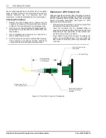
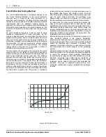
Making the Splice
In the field, a single fiber is spliced using a an SC/APC
connector. This connector must be purchased separately.
Insert both ends of the fiber to be spliced into the fusion
splicer and follow the instructions as recommended by the
manufacturer. Inspect the connection in the built-in viewer.
The connection should appear to be seamless. Ensure that
the signal loss on the display is.05 db or less. Coil the
successful splice inside the splice tray, taking care not to
exceed the bend radius parameters of the cable.
Cleaning Fiber Optic Connectors
NOTE: The process described here should not be
applied routinely. This procedure should only
be performed in cases where degraded perfor-
mance of the assembly is noted or their is evi-
dence of contamination. Excessive cleaning
may actually increase the likelihood of fiber
contamination.
Materials used for cleaning fiber-optic devices should be
consistent with the function. Wiping cloths should be made
of lint free, non-abrasive materials. Cotton swabs should


