Reference
R - 11
Form 361015-0001A
FiberPoint Structured Wiring Enclosure Installation Guide
O
PTICAL
L
INK
B
UDGET
C
ALCULATOR
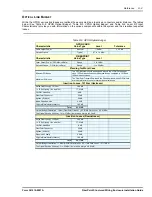
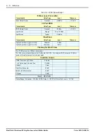
In order to more easily calculate expected optical link
budget losses within the GPON, Optical Solutions has
developed a calculator that will quickly do the work for you.
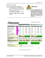
Link Budget Calculation
Link budget calculation is the end result of the PON design
calculation. The downstream and upstream receiver
sensitivity values are static, and represent the minimum
specification that OSI receivers are designed to. The
highlighted box is the final result. The column for "Mean-
3
σ
" represents optical power margin for the worst case
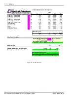
PON port at the fiber length specified. See ‘Figure R-4:
GPON Link Budget Calculator’ and ‘Figure R-5: VPON
Calculator’.
1118
IMPORTANT
IMPORTANT: If you are viewing this document
electronically, a GPON calculator has
been included on the CD or the directory
where you access this document. Refer
to file name GPON_Calculator.xls. This
calculator is also available as a
standalone tool that can be installed on
your hard drive. Contact Optical
Solutions Customer Service Department
for a copy.
NOTE: In order to utilize the calculator, you must
have Microsoft Excel, version 7.x or above
installed on your P.C.
GPON C
ALCULATOR
I
NSTRUCTIONS
The PON calculator is used as a tool to estimate the loss
for a network design consisting of any combination of
elements that are available for the PON outside plant.
OSI Specification PON loss
To include an element into the PON loss calculation, enter
a number in the highlighted, quantity column for the
number of those elements present in the design (For
example, if one 1X8 splitter is somewhere in the PON, then
enter quantity of 1. If the total length of fiber used to reach
a home is 8km, then enter quantity of 8 for fiber length).
NOTE: PON loss in the upstream direction must be 17
dB at a minimum, as the maximum power
received by the FiberDrive receiver is -14
dBm, and the FiberPoint transmitter maximum
power is 3 dBm. This is the only maximum
received power level needed for consideration
for the GPON.
For the VPON, maximum operating received power by the
video receiver is 2 dBm.
Optical splitter losses shown represent the worst case loss
for the particular line item (e.g. 1x4 splitter). Other splitters
(e.g. without connectors, installed with fusion splice only)
are available at less optical loss. If such a splitter is used,
then a small amount of (unaccounted for) margin is gained.
The 3
σ
(three sigma)
column represents the maximum loss
variation for the line item. The
σ
2
column is an intermediate
result used in calculating the sum-of-squares, total of
variance of all loss components in the PON.
Laser Power Calculation
Laser power values are static, and represent the tolerance
that OSI lasers are calibrated to. Laser power is also
corrected for minimum power output over the temperature
range that the particular laser is designed to operate in.
PON D
ESIGN
G
UIDELINES
Included here is some helpful information on designing
your system. Additional information is available in the Form
367001-0001 FiberPath 500 System Design Guidelines.
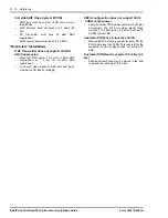
Nominal Installations
Voice/Data Only System (GPON)
•
PON loss must be at least 17 dB and no more
than 25 dB
•
PON distance must not exceed 12.5 miles (20
km)
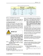
Table R-4: Laser RF Input Characteristics
Signal
1550nm Laser
Transmitter
1550nm Laser
Digital Transport Option
NTSC Video
23.5 ±.5 dBmV
N/A
Voice
N/A
N/A
Data
N/A
N/A
Digital Video
N/A
21.5 ±.5 dBmV
Input to EDFA
9 dBm
6 dBm

