Pre-Installation Requirements
2-3
Form 361015-0001A
FiberPoint Structured Wiring Enclosure Installation Guide
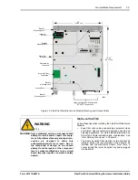
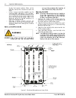
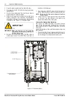
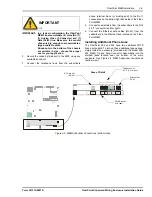
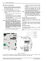
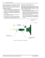
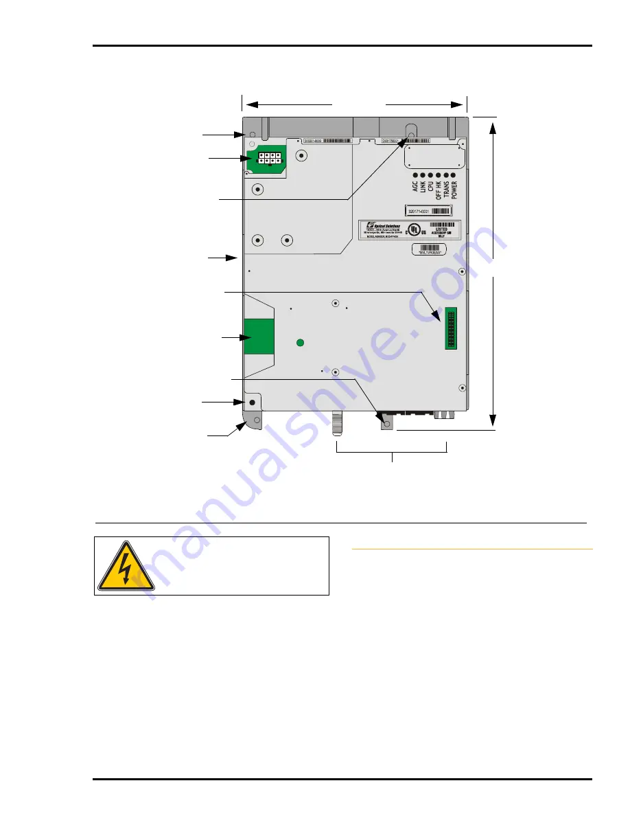
Figure 2-2:FiberPoint Main Electronics Module Mounting and Access Points
WARNING
1106
WARNING: Only authorized service personnel should
attempt to install and/or repair this equip-
ment. All problem discovery and repair pro-
cedures are designed to allow only
subassembly/module level repair. Due to
the complexity of design, no one should
attempt to make repairs at the component
level or make modifications to any circuit
board. Improper repairs can create a safety
hazard.
I
NSTALLATION
T
IPS
Follow these tips when installing the FiberPoint Electronics
Module:
•
Keep fiber optic cables and splicing equipment clean
at all times. Use manufacturer approved solvents and
cleaning applicators. For more detailed information on
Fiber Optic Cable installation and maintenance, See
‘Fiber Splicing Techniques’ in Chapter 4.
•
The single incoming fiber must be routed and spliced
inside a splice tray (not provided), which should be
installed near the electronics module. From there, a
connectorized fiber exits the splice tray and is plugged
into the MEM.
•
The single incoming fiber must be routed and spliced
inside a splice tray (not provided), which should be
installed near the electronics module. From there, a
connectorized fiber exits the splice tray and is plugged
into the MEM.
Mounting
Bracket
Ground Post
Outgoing Telephone, Ethernet and
RF CATV Connections
7.5”
(19.05 cm)
3469
Bracket
Mounting Hole
Bracket
Mounting Hole
10-1/8”
(25.72 cm)
Bracket
Mounting Hole
Bracket
Mounting Hole
Incoming
Power
Incoming Fiber
Connection
Reserved for
future use


