3-2
FiberPoint MEM Installation
FiberPoint Structured Wiring Enclosure Installation Guide
Form 361015-0001A
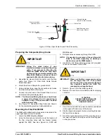
housing from several locations. Where will the
telephone lines exit the enclosure and enter the
home?
•
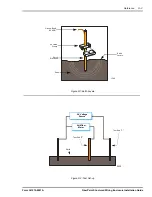
Is there a ground connection available near the
FiberPoint MEM? Depending on the installation,
you will either need to install the earth ground rod
prior to putting the unit into service or ground the
unit to the home electrical system. Refer to the
Reference Section for specific information on
proper grounding techniques.
•
What type of building material is used on the
home? Make sure you have the appropriate drills,
drill bits and fasteners for dealing with a multitude
of materials.
I
NSTALLATION
P
ROCEDURE
WARNING
1106
WARNING: High voltage electrical and pressurized
natural gas lines may be present. Make
sure you fully understand the locations of
these and all other utility connections.
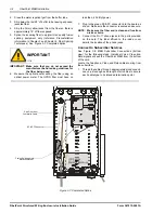
Mounting the SWE
NOTE: Structured Wiring Enclosures are available in
many sizes. For purposes of this installation
guide, a 30” SWE is used in order to accom-
modate a full featured application.
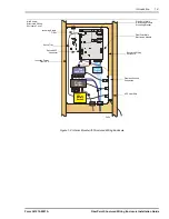
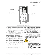
1.
Determine the location of the enclosure inside the
subscribers home. Normally, the FiberPoint MEM will
be housed inside the SWE as shown below.
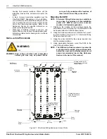
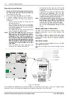
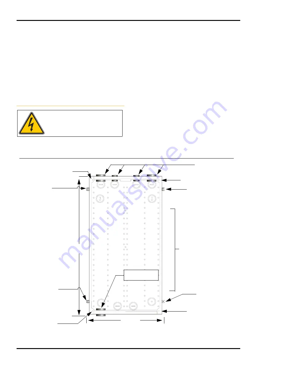
2.
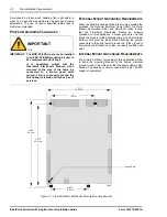
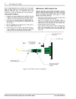
Using the Enclosure and a level, mark the four mount-
ing hole locations. See ‘Figure 3-1: Structured Wiring
Enclosure Access Points’.
3.
Using the correct drill bit for the screws required, pre-
drill the marked locations.
4.
Using appropriate fasteners, mount the SWE to the
side of the subscribers home.
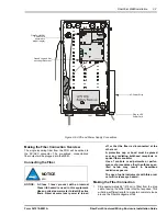
NOTE: The SWE can be flush mounted or recessed to
an interior wall provided proper airflow exists
behind the cover and that temperatures do not
exceed recommended levels (See Reference
Section in the back of this manual).
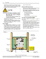
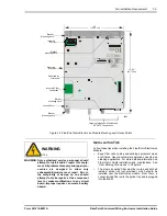
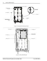
Figure 3-1: Structured Wiring Enclosure Access Points
3474
Mounting
Location
Cover
Screw
Mounting
Location
Not Shown:
Outer Cover
Mounting
Location
Cover
Screw
Cover
Screw
Mounting
Location
Multiple knock-outs for
pass through or through
the wall access
16.1”
(40.9 cm)
Multiple Knock-outs
(side and bottom) up
to 2” diameter
30”
(76.2 cm)
Cover
Mounting
Screw
Typical Composite
(Drop) Cable Entry
Point


