2-2
Section
Connections
9
2-2
Connections
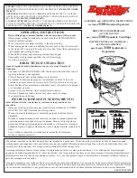
Connect the basic component as shown in the following dia-
gram. Details are provided later in this section.
Power Supply
→
(OMRON’s S82K-01524
recommended.)
*F150-VS Camera Cable (3m)
*F150-S1 Camera
*Components marked with an
asterisk are specially designed
for the V530-R150.
Other products cannot be used.
*F150-KP Console
(cable length: 2m)
Video Monitor
F150-VM Monitor
Cable (2m)
BNC Jack
(accessory)
*Use an NTSC monitor
with external video input
terminals.
OMRON’s F300-M09
recommended.
Note Turn OFF the power to the Controller before connecting or dis-
connecting cables. Connecting or disconnecting cables with
power turned ON can damage peripheral devices.
Содержание V530-R150
Страница 1: ...Cat No Z136 E1 1 V530 R150 OPERATION MANUAL 2 Dimensional Code Reader ...
Страница 2: ...V530 R150 2 Dimensional Code Reader Operation Manual Produced July 1999 ...
Страница 89: ...5 4 Section STEP 2 Setting Reading Conditions 79 8 Select 1 Read DataMatrix 9 Select Reading Settings ...
Страница 95: ...5 6 Section STEP 4 Starting Code Reading 85 3 Input reading trigger Reading is performed QRCode ABCDE12345 ...
Страница 132: ...6 2 Section SET Setting Mode 123 Line Bright X fixed Y coordinate Line Bright Y fixed X coordinate ...
Страница 197: ...Cat No Z136 E1 1 V530 R150 2 Dimensional Code Reader OPERATION MANUAL ...