Using Software Options
Part # 910-250C
139
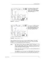
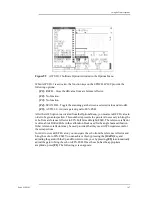
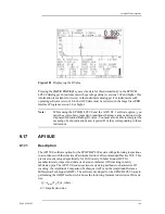
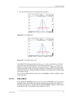
Figure 91
Adjusting DGS/AVG Calculations
This screen allows the operator to adjust portions of the DGS/AVG calculations used to
draw the curves. This makes DGS/AVG setups for a transducer useful for multiple test
pieces.
9.13.5
Relative Attenuation Measurement
Several methods for measuring the ultrasonic attenuation within a material are available.
Often, the procedure is designed to measure absolute attenuation in a material. This
usually requires an immersion test setup and a time-consuming set of measurements. For
the purpose of flaw sizing with the DGS/AVG method, it may be suitable under many
conditions to measure relative attenuation in your test piece or calibration block as
needed. This section describes one method of relative attenuation measurement that is
simple and has been found to be generally effective. There may be more suitable methods
available, and the operator must decide the most appropriate method to arrive at the values
for ACVSPEC and ACVCALBLK based on the application and local requirements.
9.13.5.1
Measurements
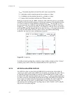
V
g
= Gain difference between two successive backwall echoes (d and 2d)
V
e
= From DGS/AVG diagram. Gain difference on backwall curve from d to 2d
9.13.5.2
Calculations
V
s
= V
g
- V
e
Sound Attenuation Coefficient:
V
s
/2d*1000 [dB/m]
∆
∆
∆
∆
∆
α
∆
=
Содержание Panametrics Epoch 4 Plus
Страница 4: ...EPOCH 4PLUS...
Страница 10: ...EPOCH 4Plus...
Страница 18: ...8 EPOCH 4PLUS...
Страница 40: ...30 EPOCH 4PLUS...
Страница 50: ...40 EPOCH 4PLUS...
Страница 54: ...44 EPOCH 4PLUS...
Страница 92: ...82 EPOCH 4PLUS...
Страница 172: ...162 EPOCH 4PLUS...
Страница 184: ...174 EPOCH 4PLUS Figure D 3 VGA Adapter Cable Olympus NDT Part EP4 C 15VGA 6 Figure D 4 VGA Adapter Cable Wire Run List...


