Using Software Options
Part # 910-250C
123
Note:
The Interface Gate option is not valid if the EPOCH 4PLUS standard Echo-
Echo mode is activated. Also, Interface Gate cannot be turned on or off
while the screen is frozen.
9.9.4
Managing Gate Positioning and Alarms
When the Interface Gate option is activated, the Interface Gate is visible on the screen.
This gate is in addition to Gate 1 (always displayed) and Gate 2 (can be turned on or off).
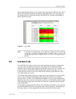
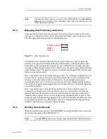
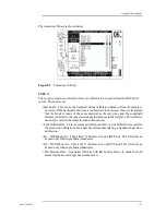
The three gates differ in appearance as illustrated below:
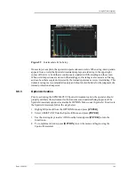
Figure 73
Gate Appearances
The Interface Gate should be positioned in the region where you expect to detect the
interface echo (generated from the reflection at the boundary of the water path and the
front surface of the test material). Set a proper gate width and level to ensure this echo
continues to break the gate threshold. It is common to set a negative logic threshold alarm
on the Interface Gate. This position results in an alarm being triggered if the interface echo
falls out of the Interface Gate.
Gate 1 is generally used as an internal flaw gate. Gate 1 is commonly positioned to cover
the area where you expect to detect echoes from internal flaws in the test material. Pay
attention to the start, width, and level of the gate as the echo height and location
corresponds to flaw size. You can choose to set a positive logic threshold alarm on Gate 1.
This results in an alarm being triggered if an echo breaks the Gate 1 threshold, indicating
a possible critical flaw.
Gate 2 is generally used to monitor the backwall echo of the test material. Gate 2 is
commonly positioned to cover the area where you expect to detect the echo from the
material backwall. Pay attention to the start, width, and level of the gate to ensure the
backwall echo is captured. You can set a negative logic threshold alarm on Gate 2. This
position results in an alarm being triggered if the backwall echo falls out of the gate. This
could indicate an obstruction (flaw) in the sound wave propagation that may prevent a
backwall echo from being received by the instrument.
9.9.5
Defining Gate Commands
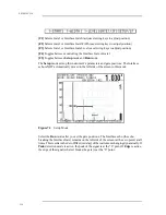
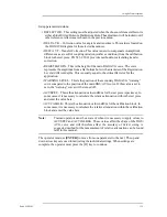
When the Interface Gate is active, press [GATE 1] to view the Interface Gate controls on
the function bar menu of the EPOCH 4PLUS.
Note:
Press [GATE 1] at any time to bring these controls back to the function bar.
Interface Gate:
Gate 1:
Gate 2
:
Содержание Panametrics Epoch 4 Plus
Страница 4: ...EPOCH 4PLUS...
Страница 10: ...EPOCH 4Plus...
Страница 18: ...8 EPOCH 4PLUS...
Страница 40: ...30 EPOCH 4PLUS...
Страница 50: ...40 EPOCH 4PLUS...
Страница 54: ...44 EPOCH 4PLUS...
Страница 92: ...82 EPOCH 4PLUS...
Страница 172: ...162 EPOCH 4PLUS...
Страница 184: ...174 EPOCH 4PLUS Figure D 3 VGA Adapter Cable Olympus NDT Part EP4 C 15VGA 6 Figure D 4 VGA Adapter Cable Wire Run List...

