41057610TH Rev. 1
4 /
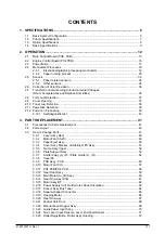
3.3.26 Roller Hopping .................................................................................................. 73
3.3.27 PXU PCB/PXM PCB, Lever Resist Sensor ...................................................... 74
3.3.28 Paper End Lever ............................................................................................... 75
3.3.29 PCO PCB (Operator Panel) .............................................................................. 76
3.3.30 Holder Gear Toner Assy ................................................................................... 77
3.3.31 Plate Latch Lever (FD), Spring Latch Lever (FD) ............................................. 78
3.3.32 Belt Cassette Assy ........................................................................................... 79
3.3.33 High Voltage Power Supply Unit, Bracket HV (BT) Assy ................................. 80
3.3.34 Eraser Bracket Assy, Eraser Bracket (KCM) Assy ........................................... 81
3.3.35 Shaft Link .......................................................................................................... 82
3.3.36 Contact (BL-R) Assy, Contact (CL-R) Assy ...................................................... 83
3.3.37 Contact (BL-L) Assy, Contact (CL-L) Assy ....................................................... 84
3.3.38 Contact SB Assy ............................................................................................... 85
3.3.39 PXC PCB .......................................................................................................... 86
3.3.40 Heat Unit Assy .................................................................................................. 87
3.3.41 Oil Roller Assy .................................................................................................. 88
3.3.42 Lever Lock Heat (L)/(R), Guide Side Heat, Spring Lock ................................... 89
3.3.43 PXL PCB .......................................................................................................... 90
3.3.44 Heat Unit Guide Assy ....................................................................................... 91
3.3.45 Holder LED Assy, LED Head ............................................................................ 92
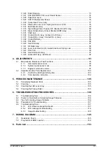
4. ADJUSTMENTS ............................................................................................. 93
4.1 Maintenance Modes and Their Functions ...................................................................... 93
4.1.1 User maintenance mode .................................................................................. 93
4.1.2 System maintenance mode .............................................................................. 95
4.1.3 Engine maintenance mode ............................................................................... 97
4.2 Adjustments after Parts Replacement ......................................................................... 100
4.2.1 Confirm the LED head driving time ................................................................. 100
4.2.2 Color deviation correction ............................................................................... 102
5. PERIODIC MAINTENANCE ......................................................................... 105
5.1 Periodically Replaced Parts ......................................................................................... 105
5.2 Cleaning ....................................................................................................................... 105
5.3 Cleaning the LED Lens Array ...................................................................................... 105
5.4 Cleaning the Pickup Roller ........................................................................................... 105
6. TROUBLESHOOTING PROCEDURES ....................................................... 106
6.1 Troubleshooting Tips ................................................................................................... 106
6.2 Points to Check before Correcting Image Problems .................................................... 106
6.3 Tips for Correcting Image Problems ............................................................................ 106
6.4 Preparation for Troubleshooting .................................................................................. 107
6.5 Troubleshooting Flow ................................................................................................... 107
6.5.1 LCD status message/trouble list ..................................................................... 107
6.5.2 LCD message troubleshooting ....................................................................... 116
6.5.3 Image troubleshooting .................................................................................... 128
7. WIRING DIAGRAM ...................................................................................... 145
7.1 Resistance Check ........................................................................................................ 145
7.2 Program/Font ROM Location ....................................................................................... 149
8. Parts List ...................................................................................................... 153
Содержание OKICOLOR 8
Страница 2: ...OKICOLOR 8 Color LED Page Printer Maintenance Manual 1999 7 14 Rev 1...
Страница 12: ...41057610TH Rev 1 11 This page intentionally left blank...
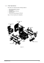
Страница 44: ...41057610TH Rev 1 43 Figure 3 1 3 2 Parts Layout...
Страница 45: ...41057610TH Rev 1 44 Figure 3 2...
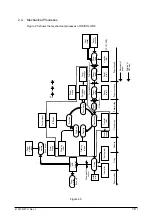
Страница 46: ...41057610TH Rev 1 45 Figure 3 3...
Страница 47: ...41057610TH Rev 1 46 Figure 3 4...
Страница 105: ...41057610TH Rev 1 104 olor check pattern...
Страница 153: ...41057610TH Rev 1 152 5 PXF PCB OPTION PENDTNR TONER UPDOWN B1 A1 B15 A15 8 1 8 1 FSENS JODEN 14 1 1 12 PXFIF...
Страница 154: ...41057610TH Rev 1 153 8 Parts List Fig 8 1 4 1 5 L J 8 9 0 A H B N N M D E C G F I 7 K 3 2 P P 6 O...
Страница 156: ...41057610TH Rev 1 155 Fig 8 2 2 1 O 3 N C 0 9 Q 6 M J 8 7 8 S H E 7 K G 4 P D R L B A F T 5...
Страница 161: ...41057610TH Rev 1 160 Fig 8 4 1 6 6 6 6 5 7 4 2 2 K 2 2 3 C E 0 I C A H H H H B C F J J D G 3 3 3 8 9 9 9...
Страница 166: ...41057610TH Rev 1 165 Fig 8 6 H B E F 2 J 4 4 I 3 3 6 9 8 7 G C D A 0 5 1 5...
Страница 168: ...41057610TH Rev 1 167 Fig 8 7 1 2 5 6 3 4...
Страница 170: ...41057610TH Rev 1 169 Fig 8 8 7 7 5 A 5 6 6 3 3 4 4 0 9 1 8 2...
Страница 172: ...41057610TH Rev 1 171 Fig 8 9 7 6 6 5 5 4 1 8 8 2 3 4 3 7...
Страница 196: ...41057610TH Rev 1 195 SEN1 CN22 CN23 CN24 5 2 PCB Layout AOLT PCB...
Страница 197: ...41057610TH Rev 1 196 6 PARTS LIST 4 D 9 3 B 6 C A E F 2 J I L 0 1 K G G G 5 7 H 9 8...


