41057610TH Rev. 1
139 /
8
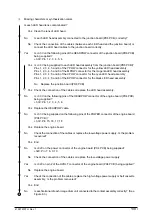
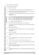
Missing characters or synthesization colors
•
Is each LED head lens contaminated?
Yes Clean the lens of LED head.
▼
•
No
Is each LED head assembly connected to the junction board (PD6 PCB) correctly?
No
Check the connection of the cables (between each LED head and the junction board) or
connect the LED head cables to the junction board correctly.
▼
•
Yes
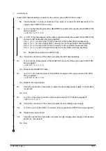
Is +3.3V on the following pins of the HEADPOW connector of the junction board (PD6 PCB)
being supplied?
+3.3V: Pin 1, 2, 3, 4, 5, 6
•
Yes Is +3.3V being supplied to each LED head assembly from the junction board (PD6 PCB)?
Pins 1, 2, 3, 4, 5 and 6 of the YPOW connector for the yellow LED head assembly
Pins 1, 2, 3, 4, 5 and 6 of the MPOW connector for the magenta LED head assembly
Pins 1, 2, 3, 4, 5 and 6 of the CPOW connector for the cyan LED head assembly
Pins 1, 2, 3, 4, 5 and 6 of the BPOW connector for the black LED head assembly
No
Replace the junction board (PD6 PCB).
▼
•
Yes Check the connection of the cables or replace the LED head assembly.
▼
•
No
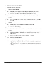
Is +3.3V on the following pins of the HEADPOW connector of the engine board (PX4 PCB)
being supplied?
+3.3V: Pin 1, 2, 3, 4, 5, 6
Yes Replace the HEADPOW cable.
▼
•
No
Is +3.3V being supplied on the following pins of the POWER connector of the engine board
(PX4 PCB)?
+3.3V: Pin 15, 16, 17, 18
Yes Replace the engine board.
▼
•
No
Check the connection of the cables or replace the low-voltage power supply. Is the problem
recovered?
Yes End
▼
•
No
Is +32V on the power connector of the engine board (PX4 PCB) being supplied?
+32V: Pin 7, 8, 9, 10
No
Check the connection of the cables or replace the low-voltage power supply.
▼
•
Yes
Is +32V on pin 2 of the HVOLT connector of the engine board (PX4 PCB) being supplied?
No
Replace the engine board.
▼
•
Yes
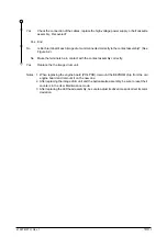
Check the connection of the cables, replace the high-voltage power supply or belt cassette
assembly. Is the problem recovered?
Yes End
▼
•
No
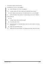
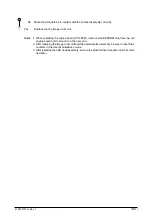
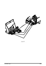
Is each terminal of each image drum unit connected to the contact assembly correctly? (See
Figure 6.3.)
A
Содержание OKICOLOR 8
Страница 2: ...OKICOLOR 8 Color LED Page Printer Maintenance Manual 1999 7 14 Rev 1...
Страница 12: ...41057610TH Rev 1 11 This page intentionally left blank...
Страница 44: ...41057610TH Rev 1 43 Figure 3 1 3 2 Parts Layout...
Страница 45: ...41057610TH Rev 1 44 Figure 3 2...
Страница 46: ...41057610TH Rev 1 45 Figure 3 3...
Страница 47: ...41057610TH Rev 1 46 Figure 3 4...
Страница 105: ...41057610TH Rev 1 104 olor check pattern...
Страница 153: ...41057610TH Rev 1 152 5 PXF PCB OPTION PENDTNR TONER UPDOWN B1 A1 B15 A15 8 1 8 1 FSENS JODEN 14 1 1 12 PXFIF...
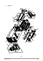
Страница 154: ...41057610TH Rev 1 153 8 Parts List Fig 8 1 4 1 5 L J 8 9 0 A H B N N M D E C G F I 7 K 3 2 P P 6 O...
Страница 156: ...41057610TH Rev 1 155 Fig 8 2 2 1 O 3 N C 0 9 Q 6 M J 8 7 8 S H E 7 K G 4 P D R L B A F T 5...
Страница 161: ...41057610TH Rev 1 160 Fig 8 4 1 6 6 6 6 5 7 4 2 2 K 2 2 3 C E 0 I C A H H H H B C F J J D G 3 3 3 8 9 9 9...
Страница 166: ...41057610TH Rev 1 165 Fig 8 6 H B E F 2 J 4 4 I 3 3 6 9 8 7 G C D A 0 5 1 5...
Страница 168: ...41057610TH Rev 1 167 Fig 8 7 1 2 5 6 3 4...
Страница 170: ...41057610TH Rev 1 169 Fig 8 8 7 7 5 A 5 6 6 3 3 4 4 0 9 1 8 2...
Страница 172: ...41057610TH Rev 1 171 Fig 8 9 7 6 6 5 5 4 1 8 8 2 3 4 3 7...
Страница 196: ...41057610TH Rev 1 195 SEN1 CN22 CN23 CN24 5 2 PCB Layout AOLT PCB...
Страница 197: ...41057610TH Rev 1 196 6 PARTS LIST 4 D 9 3 B 6 C A E F 2 J I L 0 1 K G G G 5 7 H 9 8...


