background image

 41057610TH  Rev. 1

88 /

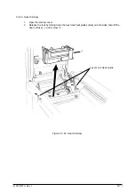
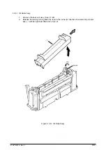
3.3.41 Oil Roller Assy

1.

Remove the heat unit assy. (See 3.3.40)

2.

Release the lock by turning down the lever in the arrow (A) direction, then slide the oil roller
assy 

1

 with its right side lifted and remove it.

1

Lever

(A)

Figure 3.3.41  Oil Roller Assy

Содержание OKICOLOR 8

Страница 1: ...Thank You for purchasing this Factory Service Manual on EBAY from PCTECHINFO Click Here for more Factory Service Manuals for other Computer and Printer Copier Manufacturers from PCTECHINFO...

Страница 2: ...OKICOLOR 8 Color LED Page Printer Maintenance Manual 1999 7 14 Rev 1...

Страница 3: ...contents of this manual are subject to change without prior notice Although reasonable efforts have been taken in the preparation of this manual to assure its accuracy this manual may still contain so...

Страница 4: ...1 Self diagnostic test 40 3 PARTS REPLACEMENT 41 3 1 Precautions for Parts Replacement 41 3 2 Parts Layout 43 3 3 How to Change Parts 47 3 3 1 Cover Assy Rear 48 3 3 2 Motor Fan 80 25 49 3 3 3 Paper E...

Страница 5: ...older LED Assy LED Head 92 4 ADJUSTMENTS 93 4 1 Maintenance Modes and Their Functions 93 4 1 1 User maintenance mode 93 4 1 2 System maintenance mode 95 4 1 3 Engine maintenance mode 97 4 2 Adjustment...

Страница 6: ...t 180 3 2 Parts Layout 182 3 3 Parts Replacement Methods 183 3 3 1 Idle rollers 184 3 3 2 AOLT PCB 185 3 3 3 Hopping motor 186 3 3 4 Feed roller 187 3 3 5 Hopping roller 188 3 3 6 Side frame L assy 18...

Страница 7: ...sor Ejection sensor Toner Low Y M C K EP Up Down Y M C K Waste toner sensor Resist Up Down Cover open switch High voltage interlock switch Heater temperature thermistor Backup temperature thermistor E...

Страница 8: ...are Electro photographric processor Paper feeder Controller CU part PU Part Operator panel Power board High voltage part PU part Figure 1 2 show the printer unit configuration Figure 1 2 Face up Stack...

Страница 9: ...0TH Rev 1 8 1 3 Option Specifications Options available for OKICOLOR 8 are as follows 1 2nd Feeder 2 RAM SIMM module 72 pin SIMM 4MB 8MB 16MB 32MB Make sure to use a set of 2 of the same volume size m...

Страница 10: ...lbs 44lbs 5 Resolution 600 dots per inch x 600 dots per inch 6 Input voltage 120VAC 5 5 15 230VAC 10 7 Power consumption Peak Typical operation Idle Power save mode 8 Frequency 50Hz or 60Hz 2 2 9 Nois...

Страница 11: ...ry 1 month max Delivery 1 month max 17_C to 27_C for assurance of full color printout quality Power off with drum and toner without drum and toner and Belt Cassette Assy with drum and toner 13 Printer...

Страница 12: ...41057610TH Rev 1 11 This page intentionally left blank...

Страница 13: ...POW 12P K600 14P KPOW 12P HEAD1 13P HEAD2 14P HEADPOW 12P HEAD3 15P FF form sensor Toner sensor x 4 ID sensor x 4 Low voltage power supply 6P 6P JST3P FAN 1 FAN 2 3P Oil PAD MSW FF motor Paper supply...

Страница 14: ...o OKI HSP Host I F Not installed TE6135 6137 16550 53C80 Engine Interface controller Operator panel OSC Reset circuit DIP SW SysAD SysCmd Control NMI INTO ExtReg INT1 Reset ColdReset VCCOK ModeIn Mode...

Страница 15: ...decompres sion and video interface functions 7 Interface control LSI This block mainly consists of PU interface control operator panel interface control EEPROM control parallel interface control and...

Страница 16: ...es the asynchronous bidirectional interface and transmits and receives 1 byte data using eight data signal leads under semi duplex control by the host When the power is turned on the compatibility mod...

Страница 17: ...ideo interface LED interface motor control sensor input video memory control main scanning color correction skew correction high voltage power control and OST EX2 functions 2 2 Engine Control Board PX...

Страница 18: ...ssing from 32 V in accordance with the control sequence from the control board When cover open state is detected 32 V supply is automatically interrupted to stop the supply of all the high voltage out...

Страница 19: ...Developing roller Power supply Toner cartridge Transfer roller Paper resist Resist roller 1 Paper feed Hopping roller Power supply Resist roller 2 Paper ejection Fixing Cleaning Transferring Paper pic...

Страница 20: ...to magnitudes of the light beams Thus a latent image is formed on the surface of the OPC drum according to the resulting surface potentials 4 Developing and recovery of excessive toner This process a...

Страница 21: ...e lower surface of the paper The negatively charged paper is electrostatically attracted to the pickup roller With this the paper is in close contact with the conveying Belt and conveyed steadily 2 Pa...

Страница 22: ...rum is reduced according to magnitudes of the light beams and a latent image is formed on the surface of the OPC drum according to the resulting surface potentials 3 Charging This process applies a DC...

Страница 23: ...ller The latent image on the surface of the OPC drum is made visible with the toner 5 Developing This process applies toner to the latent image on the surface of the drum to convey it into a toner ima...

Страница 24: ...oller and applies positive charge opposite to the charge of the toner from under the paper When a positive high voltage is applied to the transfer roller from the power supply the positive charge indu...

Страница 25: ...he heat roller is heated up by the 800 watt heater or a halogen lamp provided in the heat roller The temperature of the heat roller surface is controlled by a thermistor in contact with the surface of...

Страница 26: ...ly AC switch transfer roller x 4 light rejector x 4 transfer belt unit ID unit up down actuater belt cleaning high voltage power supply pick up roller pinch roller up down transfer belt 1st tray 2nd t...

Страница 27: ...pulse motor turns in the arrow direction a and drives the hopping roller in the direction of b The hopping roller drives the resist roller Each of the one way clutch gears A B and C has a one way clut...

Страница 28: ...e paper until it hit the resist roller 1 This operation corrects any paper skew b Conveying 1 After paper hopping is completed the pulse motor turns right in the direction of b to drive the resist rol...

Страница 29: ...A Idle gear B Cam One way clutch gear B Sensor position Up down Pinch roller Entrance sensor Resist roller 2 Form sensor a b When the pulse motor of the front feeder turns right in the direction of A...

Страница 30: ...lutch 2 When the rear edge of the paper passes by the Entrance sensor 2 the pulse motor of the front feeder turns left in the direction of b to drive the cam The cam moves down the pinch roller 2 unti...

Страница 31: ...ction of a to drive the hopping roller The paper is fed until the Entrance sensor 2 turns on Although the one way clutch gear B is also rotating the pinch roller 2 does not drive the up down cam by me...

Страница 32: ...r of the I O unit The I D unit moves up as shown in Figure 2 6 b The EP drum rotates freely Figure 2 6 a When the pulse motor see Figure 2 6 a turns right CW the EP drum gear turns left CCW and the up...

Страница 33: ...41057610TH Rev 1 32 Figure 2 6 b I D unit up down actuator Up down lever I D unit Figure 2 6 c Up down lever I D unit...

Страница 34: ...are lu bricated and cleaned by a single pulse motor When the heat roller pulse motor turns right in the direction of a the heat roller and the backup roller turn left in the direction of a to fix a t...

Страница 35: ...width of the paper sheet Detects the front edge of the conveyed paper sheet and determines the length of the paper sheet from elapsed time before the front edge of the paper reaches the sensor Detect...

Страница 36: ...e up or down position 5 Waste toner sensor This sensor judges whether the waste toner cartridge is full by measuring a time period at which the sensor lever turns on periodically When the time period...

Страница 37: ...rint out the preset color chart compare the printed color chart by the original color chart and enter the amount of color deviation of each color from the operator panel or from the host computer OKIC...

Страница 38: ...jam Convey jam Ejection jam Form size error Conditions Three hopping operations are made but the Form Feed sensor Entrance does not turn on a preset time after the Form Feed sensor 1 turns on The eje...

Страница 39: ...ven when the magnet on the stirring bar reaches the maximum height since the other side is being dipped in the toner the stirring bar is pushed by the stirring gear Operation during toner low state Wh...

Страница 40: ...for 2 cycles 1 965 sec x 2 or more then the Toner Sensor Alarm is activated The toner sensor is not monitored while the drum motor is in halt 2 11 Page Size Detection The four tab pieces are driven a...

Страница 41: ...ORing high and low addresses to prepare 16 bit data units writing a preset 16 bit data pattern in RAM reading the contents of RAM and comparing the data read from RAM by the data written in RAM Check...

Страница 42: ...he equipment or floor 3 PARTS REPLACEMENT The section explains the procedures for replacement of parts assemblies and units in the field Only the removal procedures are explained here Reverse the proc...

Страница 43: ...Service Tools No No 1 100 Philips screwdriver Q ty Place of use Remarks Service Tools 1 2 3 4 5 6 8 No 2 200 Philips screwdriver Magnetized No 3 100 screwdriver No 5 200 screwdriver Digital multimete...

Страница 44: ...41057610TH Rev 1 43 Figure 3 1 3 2 Parts Layout...

Страница 45: ...41057610TH Rev 1 44 Figure 3 2...

Страница 46: ...41057610TH Rev 1 45 Figure 3 3...

Страница 47: ...41057610TH Rev 1 46 Figure 3 4...

Страница 48: ...l Hopper Assy 3 3 22 PCO PCB 3 3 29 Holder Gear Toner Assy 3 3 30 Plate Latch Lever FD 3 3 31 High Voltage Power Supply Unit 3 3 33 Eraser BKT Assy 3 3 34 Lever Lock Heat L R 3 3 42 PXL PCB 3 3 43 Hea...

Страница 49: ...7610TH Rev 1 48 3 3 1 Cover Assy Rear 1 Unscrew 2 screws 1 then lift the cover assy rear 2 a little bit then remove the cover assy rear by releasing the lock of two claws 1 2 Figure 3 3 1 Cover Assy R...

Страница 50: ...25 1 Remove the cover assy rear See 3 3 1 2 Unscrew 2 screws 1 3 Detach the motor fan 2 from the guide with its right side lifted then draw the motor fan 4 Unplug the cable 3 then remove the motor fa...

Страница 51: ...ame eject assy and the guide paper eject assy 1 Remove the cover assy rear See 3 3 1 2 Open the top cover 3 Unscrew 4 screws 1 then remove the frame eject assy 2 4 Remove the guide paper eject assy 3...

Страница 52: ...unit assy 1 Remove the cover assy rear See 3 3 1 2 Detach the cable from the cable clamp 1 by releasing its lock 3 Unscrew 8 screws 2 then remove the cover assy stacker 4 Unscrew 4 screws 4 then remo...

Страница 53: ...4 Detach the cable from the cable clamp 1 by releasing its lock 5 Remove connections of 4 connector cables 2 and 4 cables 3 6 Unscrew 4 screws 4 then remove the PCB 5 7 Unscrew 2 screw 6 then remove...

Страница 54: ...40 2 Remove the cover assy rear See 3 3 1 3 Remove the cover assy stacker See 3 3 4 4 Remove the frame assy upper See 3 3 5 5 Detach the cable from the cable clamp 1 by releasing its lock 6 Unscrew 2...

Страница 55: ...1 Remove the plate support assy L and R See 3 3 6 2 Unscrew 2 screws 1 then remove the limiter 2way L 2 and the plate guide L 3 3 Unscrew 2 screws 4 then remove limiter 2way R 5 and the plate guide R...

Страница 56: ...the cover assy side R 5 Unplug the operator panel cable 5 from the PCM PCB 6 Open the FDR unit front in the arrow direction 7 Unscrew 2 screws 6 then remove the cover assy OP panel7 8 Unscrew 2 screw...

Страница 57: ...lock of the claw by lifting the cover assy side R 2 a little bit then remove the cover assy side R 3 Unscrew 2 screws 8 to remove the plate shieled CU 9 4 Unscrew 3 screws 3 to remove the plate shield...

Страница 58: ...Open the top cover 2 Remove the cover assy side R frame side L cover assy OP panel and the cover front R See 3 3 8 3 Unplug the cable 1 and unscrew 2 screws 2 2 collars 4 and then remove the motor fa...

Страница 59: ...remove them at the same time 1 Remove the PCB assy PCE See 3 3 9 2 Unscrew 5 screws 1 then remove the cover CU2 3 Unplug all the cables 5 connected to the PXF PCB 3 and PX4 PCB 4 4 Unscrew 5 screws 6...

Страница 60: ...ll the cables connected to the PXF PCB then remove the PX4 PCB See 3 3 11 Be careful not to damage the connector when unplugging cables connected to the PXF PCB 4 Remove the heat unit assy See 3 3 40...

Страница 61: ...and remove 4 plate Earth 9 and 4 lever Up Dn 2 1 3 Unplug all the cables 2 connected and unscrew 4 screws 3 then remove the main motor A assy 4 4 Unplug all the cables 5 connected and unscrew 3 screws...

Страница 62: ...requires adjustment 1 Remove the PCB assy PCM See 3 3 9 2 Remove the cover CU See 3 3 11 3 Remove the 4 Plate Earth and 4 lever Up Dn 2 See 3 3 13 4 Release the lock with the shaft by spreading the cl...

Страница 63: ...1057610TH Rev 1 62 3 3 15 Motor Assy BT 1 Remove the main motor B assy See 3 3 13 2 Unplug 2 cables 1 connected and unscrew 2 screws 2 then remove the motor assy BT 3 3 1 2 Figure 3 3 15 Motor Assy BT...

Страница 64: ...he cover assy side R and the cover rear L See 3 3 8 3 Unplug the cable 1 4 Remove the holder inlet 3 by unscrewing 2 screws 2 then remove the power switch 4 and unplug the AC socket 5 5 Draw the power...

Страница 65: ...Toner 1 Remove the power supply unit See 3 3 16 2 Unscrew the screw 1 then remove the sensor assy box toner 2 together with the bracket 3 3 Unscrew the screw 4 then remove the sensor assy box toner 2...

Страница 66: ...supply unit See 3 3 16 Do not remove the power switch and AC socket from the holder inlet 2 Unplug the cable 1 3 Remove cable 2 screw 5 bracket 6 and cable 7 in order and then take off SW from bracke...

Страница 67: ...el and the cover front R See 3 3 8 2 Unscrew 2 screws 1 and unplug the cable 2 then remove the bracket hopping motor 3 Be careful not to lose the gears 5 6 and 7 which slip off at this time 3 Unscrew...

Страница 68: ...1 Remove the bracket hopping motor See 3 3 19 2 Remove the spacer 4 first and release the locks with the shaft by spreading the claws of the gear one way 1 2 and 3 then remove the gear one ways 3 2 1...

Страница 69: ...8 2 Remove the cover CU See 3 3 11 3 Unscrew the screw 8 and remove the cable 9 4 Unplug the cable 1 and unscrew the screw 2 then remove the bracket FF shaft 3 5 Remove 2 E rings 4 then remove the fee...

Страница 70: ...eed Hopper Assy 1 Open the manual feed hopper assy 2 Release the engagement between the holder and the link then remove the manual feed hopper assy Be careful not to damage the holder Holder Link 1 Fi...

Страница 71: ...and the cover front L See 3 3 8 2 Remove the feeder unit front See 3 3 21 3 Unscrew 4 screws 1 then draw out the guide paper input assy 2 from the left side by rotating its upper part Be careful not...

Страница 72: ...3 3 23 2 Release the engagement with the guide by pressing 2 lever input sensors 2 in the arrow direction then remove them 3 Release the engagement with the guide by pressing the lever 2nd feed sensor...

Страница 73: ...en 2 roller registrations 4 Removal of the roller assy hopping 6 Remove the bush 5 and the bearing 6 7 Remove E rings 9 of the sub roller hopping at both sides of hopping roller and then release the l...

Страница 74: ...sy hopping See 3 3 25 and remove the 2 sub roller hopping guide 3 Be careful not to lose the knock pin which slips off together when removing the roller assy hopping 2 Detach the roller hopping 2 from...

Страница 75: ...remove them at the same time 1 Remove the guide paper input assy See 3 3 23 2 Unscrew 4 screws 1 and unplug the cable 2 then remove the PXU PCB 3 and PXM PCB 4 at the same time 3 Remove the lever res...

Страница 76: ...41057610TH Rev 1 75 3 3 28 Paper End Lever 1 Remove the guide paper input assy See 3 3 23 2 Remove the paper end lever 1 by releasing the engagement with the guide 1 Figure 3 3 28 Paper End Lever...

Страница 77: ...the cover assy OP panel See 3 3 8 2 Unscrew 4 screws 1 and unplug the operator panel cable 2 6 Remove the PCO PCB 3 by releasing 6 claws Be careful not to drop the LCD Liquid Crystal Display 4 and 5...

Страница 78: ...r Toner Assy 1 Remove the cover assy side R cover assy OP panel cover front R and the cover rear L See 3 3 8 2 Unplug the cable 1 and unscrew the screw 2 then remove the holder gear toner assy 3 2 3 1...

Страница 79: ...3 8 2 Open the cover CU See 3 3 11 3 Unplug the cable 1 4 Unscrew 4 screws 4 then remove the stay upper front 5 5 Unscrew 2 screws 2 then remove the bracket SW side 3 6 Remove the plate latch lever F...

Страница 80: ...rawing the cover knob then open the cover assy side L 3 Turn the waste toner box box toner assy 1 to the left by pressing it down then remove it 4 Draw out the belt cassette assy 2 by lifting it a lit...

Страница 81: ...See 3 3 32 2 Unscrew 2 screws 1 with the stacker cover opened then remove the plate HV 2 3 Unplug the cable 3 and 7 codes 4 4 Unscrew 2 screws 5 then remove the high voltage power supply unit 6 5 Rem...

Страница 82: ...nector 2 5 Release the screw 7 and then remove the eraser bracket assy 3 Removing the eraser bracket KCM assy 5 Remove the screw 1 and the connector 2 6 Release the lock of the claw then release the e...

Страница 83: ...link 7 by pressing it in the arrow C direction and turning its left side under the contact BL L assy 6 Detach the sensor assy T KCM 1 bracket sensor T KCM 2 spring support R 4 lever link R 5 and the...

Страница 84: ...ge power supply unit See 3 3 33 4 Remove the shaft link See 3 3 35 Removal of the contact BL R assy 5 Unscrew 2 screws 1 and unplug the cable 2 then remove the contact BL R assy 3 Removal of the conta...

Страница 85: ...See 3 3 35 Removal of the contact BL L assy 2 Unscrew 2 screws 1 then remove the contact BL L assy 2 Removal of the contact CL L assy 3 Unscrew 2 screws 3 then remove the contact CL L assy 4 2 4 3 1...

Страница 86: ...Assy 1 Remove the contact BL L assy and contact CL L assy See 3 3 37 2 Unscrew 3 screws 1 then remove the plate blink 2 3 Unplug 7 codes 3 4 Unscrew 3 screws 4 then remove the contact SB assy 5 3 1 3...

Страница 87: ...5 5 Remove the gear heat assy See 3 3 12 6 Remove the roller assy hopping See 3 3 25 7 Remove the holder gear toner assy See 3 3 30 8 Remove the high voltage power supply unit See 3 3 33 9 Unplug the...

Страница 88: ...40 Heat Unit Assy 1 Open the stacker cover 2 Release the lock by turning down the lever lock heat guides blue on both sides then lift the heat unit assy 1 and remove it 1 Lever Lock Heat Guide Figure...

Страница 89: ...ller Assy 1 Remove the heat unit assy See 3 3 40 2 Release the lock by turning down the lever in the arrow A direction then slide the oil roller assy 1 with its right side lifted and remove it 1 Lever...

Страница 90: ...are the same Here describes the method for right side 1 Remove the heat unit assy See 3 3 40 2 Unscrew 2 screws 1 then remove the guide side heat 2 3 Remove the E ring 3 then lever lock heat R 4 Be ca...

Страница 91: ...eject assy See 3 3 3 2 Remove the belt cassette assy See 3 3 32 3 Remove the heat unit assy See 3 3 40 4 Unplug the cable 1 and the screw 2 then remove PXL PCB 3 5 Release the lock of the claw then re...

Страница 92: ...Remove the paper eject assy See 3 3 3 3 Remove the gear heat assy See 3 3 12 4 Remove the belt cassette assy See 3 3 32 5 Open the stacker cover and remove the heat unit assy See 3 3 40 6 Unscrew 4 s...

Страница 93: ...spreading the holder LED assy 2 a little bit Be careful not to lose the spring 4 which slips off together 3 Remove the holder LED assy 2 by spreading the A part of the guide holder a little bit with...

Страница 94: ...ng starts 3 To exit this mode shut off power to the page printer This is the only one way to exit this mode c Resource save area Sets the resource saving area This menu item appears when the option PS...

Страница 95: ...RESETTING RESET HEX DUMP ON LINE HEX DUMP RESOURCE SAVE AUTO OFF 400KB 900KB 1 6MB 2 5MB 19 6MB 22 5MB RECEIVE BUFFER AUTO 100KB 512KB 1MB ECP ENABLE DISABLE OP MENU ENABLE SETTING EEPROM DISABLE X A...

Страница 96: ...ery HSP ERROR count display HSP ERROR count reset 1 Page count display The total number of pages counted at the engine is displayed on the LCD 2 Page count printing enable disable This function select...

Страница 97: ...ssing ENTER key After completing the process PAGE CNT nnnnnn PAGE PRT DISABLE ENABLE CONT PRT CONT PRT CONT PRT PRINTING CANCELLED ON LINE SW Press EEPROM EEPROM EEPROM RESET RESETTING RESET HSPERR RE...

Страница 98: ...Sets the time of driving each LED head 2 Drum count display CYAN MAGENTA YELLOW BLACK Displays the number of revolutions of each EP drum counted by the engine on the LCD 3 Total drum count display CY...

Страница 99: ...er pressing ENTER key After completing the process CYAN LED HEAD No 1 SETTING EEPROM No 2 No 16 No 17 No 32 MAGENTA LED HEAD No 1 SETTING EEPROM No 2 No 16 No 17 No 32 YELLOW LED HEAD No 1 SETTING EEP...

Страница 100: ...TA DRMCNT nnnn Magenta DRMCNT T nnnnnnn Yellow DRMCNT nnnn Yellow DRMCNT T nnnnnnn BLACK DRMCNT nnnn Black DRMCNT T nnnnnnn FUSER COUNT nnnn BELT COUNT nnnn Oil Roller Count nnnnnnn T1 POSITION 0 mm S...

Страница 101: ...embly Reset the belt counter and correct color deviations EEPROM PU block Correct color deviations Oil Roller Reset the oil roller counter Other parts Correct color deviations if any 4 2 1 Confirm the...

Страница 102: ...on level Parameter value Illumination level displayed on LCD of LED head displayed on LCD of LED head 1 155 17 53 57 2 145 154 18 50 52 3 136 144 19 47 49 4 127 135 20 44 46 5 119 126 21 41 43 6 111 1...

Страница 103: ...After a color chart is printed out the menu shows the ADJUST 1 mode for entering a correction value for the left 1 yellow chart d Enter correction values for 1 left yellow chart 2 middle yellow chart...

Страница 104: ...JUST COLOR BALANCE ADJUST 0 1 ADJUST 7 1 ADJUST 7 1 ADJUST 1 1 LANGUAGE PRINT PATTERN EXIT ENTER ADJUST 0 1 ADJUST 0 2 ADJUST 0 9 PRINT EXCUTE PRINT PATTERN COLOR REG ADJUST PRINT PATTERN COLOR REG AD...

Страница 105: ...41057610TH Rev 1 104 olor check pattern...

Страница 106: ...s shall be replaced periodically If not replaced the printout quality may not be assured and in extreme cases the page printer may be in trouble The above periodic parts replacement is carried out by...

Страница 107: ...run in proper ambient conditions 2 Have the supplies toner and the routine replacement part image drum cartridge been replaced properly 3 Is the paper normal See paper specifications section 4 Has the...

Страница 108: ...the liquid crystal display LCD in the operator panel Take proper corrective action as directed by messages that are displayed on the LCD 6 5 Troubleshooting Flow If troubles should develop in this pri...

Страница 109: ...xpand RAM Check the size of paper in the tray or whether two or more paper sheets are fed at a time When the cover is opened and closed this error is reset and print ing resumes If this error occurs f...

Страница 110: ...is reset and printing resumes If this error oc curs frequently go to 6 5 2 Sets the default values in EEPROM and it ll be recovered automatically Indicates that a paper coming out of the tray jammed...

Страница 111: ...rd Turn on the power of the page printer again If this error still occurs replace the main board PCE PCB When replacing the main board PCE PCB demount the EEPROM chip from the old main board and remou...

Страница 112: ...F Blink Undefined Undefined Undefined Undefined OFF Blink Make sure that the surrounding temperature stays 10 t 50 C If this condition is not satisfied adjust the surrounding temperature otherwise sat...

Страница 113: ...on the power of the page printer again If this error still occurs replace the engine board PX4 PCB or the front feed assembly See Chapter 6 5 2 See Chapter 6 5 2 Check the connection between the engin...

Страница 114: ...gine board When re placing the main board demount the EEPROM chip from the old main board and remount it on the new main board Turn on the power of the page printer again If this error still occurs re...

Страница 115: ...Argument error Engine background error the power of the page printer again If this error still occurs replace the program ROM of the main board PCE PCB or the main board When replacing the main board...

Страница 116: ...TLB exception Store Address error exception Load or Instruc tion Fetch Address error exception Store Bus error exception Instruction Fetch Bus error exception Data Load or Store System call exception...

Страница 117: ...rror 3 4 I D Unit Up Down Error 4 5 Fusing Unit Error 5 6 Fan Motor Error 6 7 Cannot receive data from parallel interface 7 Note When replacing the main board PCE PCB and the engine board PX4 PCB demo...

Страница 118: ...lied on the PU connector of the main board PCE PCB Pin 6 15 26 35 5V Pin 1 3 5 11 20 21 40 0V Yes Replace the main board No Does a voltage of 5V are being supplied on the Power connector of the engine...

Страница 119: ...lever and check its signal on the related pin of the PXFIF connector of the junction board PXF PCB Pin B8 for FF sensor 1 Pin A7 for FF sensor 2 No Replace the junction board PXF PCB Yes Check the co...

Страница 120: ...board PXF PCB operation properly Operate each sensor lever and check its signal on the related pin of the PXFIF connector of the junction board PXF PCB Pin A7 for FF sensor 2 No Replace the junction...

Страница 121: ...y Operate the lever of the Write sensor and check its signal on the related pin of the PXFIF connector of the junction board PXF PCB Pin A8 for Write sensor No Replace the junction board PXF PCB Yes C...

Страница 122: ...of a paper pass by the Exit sensor Yes Is the sensor lever in a normal operation No Replace the defective sensor lever Exit sensor Yes Is the Exit sensor in a normal operation Operate the sensor lever...

Страница 123: ...Check the connection of the signal cable or replace the sensor board PXL PCB Yes Replace the engine board No Is the Faceup stacker open or closed completely No Open or close the faceup stacker complet...

Страница 124: ...e sensor board PXM PCB Yes Does the Write sensor lever work correctly No Replace the Write sensor lever Yes Does the Write sensor work correctly Operate the sensor lever and check its signal on the re...

Страница 125: ...gine board Yes Each IDU sensor lever work correctly No Check the gear engagement and the sensor lever operation or replace the gear or the sensor lever Yes Is each IDU sensor work correctly Cover up f...

Страница 126: ...Yes Is the voltage being supplied on Pin4 of the THERM connector of the engine board PX4 PCB normal Normaly Voltage between 0 03V and 0 25V No Replace the engine board Yes Replace the fusing unit No N...

Страница 127: ...No Replace the fan of the low voltage power supply Yes Check the connection of the cable or replace the low voltage power supply Yes Is the Engine board fan rotating after the page printer is powered...

Страница 128: ...of Parallel Interface in menu 2 to ENABLE No Set the Bidirectional Communication of Parallel Interface in menu 2 to DISABLE Is Data printed out Yes End No Is Parallel interface cable connected correc...

Страница 129: ...age are blurred or peeled off when toached with finger 6 Cyclical printout defects Figure 6 2 E 7 Missing characters or colors 8 Poor synthesization Colors 9 Printout colors different from original co...

Страница 130: ...W connector for the magenta LED head assembly Pins 1 2 3 4 5 6 of the CPOW connector for the cyan LED head assembly Pins 1 2 3 4 5 6 of the BPOW connector for the black LED head assembly No Replace th...

Страница 131: ...terminals be in contact with the contact assembly correctly Yes Replace the the image drum unit Notes 1 When replacing the engine board PX4 PCB demount the EEPROM chip from the old engine board and re...

Страница 132: ...he following pins of the HEADPOW connector of the junction board PD6 PCB being supplied 3 3V Pin 1 2 3 4 5 6 Yes Is 3 3V being supplied on the following pins of the cable connector between the junctio...

Страница 133: ...al of each image drum unit connected to the contact assembly correctly See Figure 6 2 No Make the terminals be in contact with the contact assembly correctly Yes Replace the the image drum unit Notes...

Страница 134: ...for the black LED head assembly No Replace the junction board PD6 PCB Yes Check the connection of the cables or replace the LED head assembly No Is 3 3V on the following pins of the HEADPOW connector...

Страница 135: ...t cassette assembly be sure to reset their counters in the User Maintenance mode 3 After replacing the LED head assembly be sure to adjust its drive time and correct its color deviation No Is each ter...

Страница 136: ...the engine board to the junction board correctly Yes Check the connection of the cables or replace the engine board PX4 PCB Is the problem recovered Yes End No Is Each terminal of each image drum uni...

Страница 137: ...CB connected to the junction board correctly No Connect the boards correctly Yes Check the connection of the cables or replace the engine board PX4 PCB Is the problem recovered Yes End No Is each term...

Страница 138: ...the regulation See Figure 6 1 It s about between 90 ohms and 700 ohms at room temperature of 0 C to 43 C No Replace the fusing unit assembly Yes Is resistance range of the backup roller thermistor un...

Страница 139: ...m Image Drum Replace the image drum unit 44 0 mm Developing Rooler Replace the image drum unit 28 3 mm Toner Supply Rooler Replace the image drum unit 28 3 mm Charging Roller Replace the image drum un...

Страница 140: ...d assembly No Replace the junction board PD6 PCB Yes Check the connection of the cables or replace the LED head assembly No Is 3 3V on the following pins of the HEADPOW connector of the engine board P...

Страница 141: ...cing the engine board PX4 PCB demount the EEPROM chip from the old engine board and remount it on the new one 2 After replacing the image drum unit and the belt cassette assembly be sure to reset thei...

Страница 142: ...lem recovered Yes End No Is engine board PX4 PCB connected to the junction board PD6 PCB correctly No Connect the boards correctly Yes Check the connection of the cables or replace EEPROM of the engin...

Страница 143: ...d assembly No Replace the junction board PD6 PCB Yes Check the connection of the cables or replace the LED head assembly No Is 3 3V on the following pins of the HEADPOW connector of the engine board P...

Страница 144: ...cing the engine board PX4 PCB demount the EEPROM chip from the old engine board and remount it on the new one 2 After replacing the image drum unit and the belt cassette assembly be sure to reset thei...

Страница 145: ...41057610TH Rev 1 144 Charge Roller G r o u n d D e v e l o p i n g R o l l e r T o n e r S u p p l y R o l l e r Figure 6 3...

Страница 146: ...Resistance Between pins 1 and 2 7 1 Between pins 3 and 4 7 1 Between pins 1 and 2 7 1 Between pins 3 and 4 7 1 Between pins 1 and 2 7 1 Between pins 3 and 4 7 1 Belt motor YIDU motor MIDU motor White...

Страница 147: ...ns 1 and 2 7 1 Between pins 3 and 4 7 1 Between pins 1 and 2 7 1 Between pins 3 and 4 7 1 Between pins 1 and 2 7 1 Between pins 3 and 4 7 1 CIDU motor BIDU motor Resist motor Blue Blue Blue Blue M 1 2...

Страница 148: ...rown Brown Brown M 1 2 3 4 Unit Circuit Diagram Illustration Resistance Between pins 1 and 2 7 1 Between pins 3 and 4 7 1 Between pins 1 and 2 7 1 Between pins 3 and 4 7 1 Heater motor FF motor White...

Страница 149: ...V 1 FANALM N 3 0 V 2 M White Red Black 38 V 1 FANALM N 3 0 V 2 M White a b c d Thermostat Heater Backup roller Thermistor Between pins c and d 205k at 25 C Between pins e and f 205k at 25 C Between p...

Страница 150: ...41057610TH Rev 1 149 7 2 Program Font ROM Location 1 PCE PCB PSIMMH PSIMML CS02 CS04 CS01 CS03 PANEL MUPIS CENT SIMM0_L SIMM1_L SIMM0_H SIMM1_H PU E2ROM...

Страница 151: ...41057610TH Rev 1 150 2 PX4 PCB PXFIF FAN1 FF YIDREG MCKID HETBELT HVOLT PSIZE COVOPN HEAD3 HEAD2 HEAD1 HEADPOW SW1 CUIF FAN2 RSENS THERM POWER 1 2 29 30 A1 B1 A15 B15 IC4...

Страница 152: ...41057610TH Rev 1 151 3 Power Supply PCB TR Y TR M TR C TR B CN1 DB B DB C GND CH SB DB M DB Y 4 PCO PCB D4 D3 D2 D1 D5 D6 SW1 SW5 SW2 SW6 SW3 SW7 SW4 SW8...

Страница 153: ...41057610TH Rev 1 152 5 PXF PCB OPTION PENDTNR TONER UPDOWN B1 A1 B15 A15 8 1 8 1 FSENS JODEN 14 1 1 12 PXFIF...

Страница 154: ...41057610TH Rev 1 153 8 Parts List Fig 8 1 4 1 5 L J 8 9 0 A H B N N M D E C G F I 7 K 3 2 P P 6 O...

Страница 155: ...ssy_Rear Cover_Rear Stacker_Faceup Support_Stacker Cover_Assy_Stacker Cover_Assy_Side R Cover_Side R Frame_Side R Cover_Front R Cover_Assy_OP_Panel Cover_Sub_Assy_OP_Panel Cover_Front L Cover_Assy_Sid...

Страница 156: ...41057610TH Rev 1 155 Fig 8 2 2 1 O 3 N C 0 9 Q 6 M J 8 7 8 S H E 7 K G 4 P D R L B A F T 5...

Страница 157: ...mable Consumable Name Motor_Fan 80 25 Frame_Eject_Assy Guide_Paper_Eject_Assy Frame_Upper_Assy Power_Unit_ACDC_Switching Power_Unit_ACDC_Switching FDR_Unit__Front Plate_FF_Link Bracket_FF_Link Guide_P...

Страница 158: ...41057610TH Rev 1 157 Fig 8 3 x y G C w m 0 Z B 8 9 P 1 M N e L c z d f j j z 4 W V 0 a D i n p q H F X J r Y 3 K I S R Q 7 T 2 t s u l O k h 5 o g h v A E b...

Страница 159: ..._Paper_End Sensor_Assy_Box_Toner Frame_Side L Frame_Side R Contact_SB_Assy Plate_Blind Guide_Side_Heatunit Spring_Lock L Spring_Lock_Heat Lever_Lock_Heatunit L Lever_Lock_Heatunit R Limiter 2Way L Lim...

Страница 160: ...ller_Boss_Assy Guide_Paper_Input_A Lever_Input_Sensor Lever_2ndFeed_Sensor Shaft_Hoppingroller 1st Bracket_Switch Holder_Switch Spring_Eject_Heat Knock_Pinn CONN_Cord_Wire Bracket_Switch Side InterLoc...

Страница 161: ...41057610TH Rev 1 160 Fig 8 4 1 6 6 6 6 5 7 4 2 2 K 2 2 3 C E 0 I C A H H H H B C F J J D G 3 3 3 8 9 9 9...

Страница 162: ...2 3 Includes Item6 Includes Item6 Name Cotact_ BL_L Assy Plate_Earth LK Bearing Contact_ CL_L Assy Contact_BKT BL_R Assy Photo_Interrupter Contact_BKT CL_R Assy Eraser_BKT_Assy Eraser_BKT KCM _Assy Sh...

Страница 163: ...41057610TH Rev 1 162 Fig 8 5 1 2 X Z e E k j h i Y a L M L b B K N O b b 6 6 34 c d T V U C G R H H g S P Q D E F I 5 J A A 5 5 7 A W 0 9 8 A A C B C D B D...

Страница 164: ...Designated in Fig 8 4 Gear_Heat_Assy Motor_Assy_Belt Main_Motor A _Assy Main_Motor B _Assy Gear_Oneway Z30 Lever_Up Dn2 YMC Bracket_Hopping_Motor Gear_Idle 92 Gear_Feed 118 17 Gear_Oneway Z48 74 Motor...

Страница 165: ...04901 40447201 Remarks Designated in Fig 8 3 Name Belt_Motor_Mech_Assy Photo_Interrupter Gear_Heat_Mech_Assy Lever_Up Dn2 K Plate_Earth LKR Plate_Shield CU CONN_Cord_Wire EPROM EPROM PROM_Control PROM...

Страница 166: ...41057610TH Rev 1 165 Fig 8 6 H B E F 2 J 4 4 I 3 3 6 9 8 7 G C D A 0 5 1 5...

Страница 167: ...g 8 5 Name Frame_Upper Holder_LED_Assy Guide_Holder Spring_Head Spring_EP Board_PD6 Plate_Oil_Sensor AMP2P_MSW Holder_SW Plate_Support_ L Assy Torsion_Spring A Plate_Support_ R Assy Torsion_Spring B F...

Страница 168: ...41057610TH Rev 1 167 Fig 8 7 1 2 5 6 3 4...

Страница 169: ...1 1 Parts No 40449801 50928901 56730640 40177701 40368301 53346601 Remarks Name Guide_Cassette R Sub_Assy Spring_Detector Square_shaped_connector Connector_Cord Board PXC Plate_Earth link 500 3 3 3 3...

Страница 170: ...41057610TH Rev 1 169 Fig 8 8 7 7 5 A 5 6 6 3 3 4 4 0 9 1 8 2...

Страница 171: ...501 40135301 40308601 40135301 40449601 Remarks Name Frame_Motor ID1 Motor_Pulse ID Gear_ 25 75 Gear_Helical 67 43 24 Gear_Helical 67 18 Gear_Z53 44 Bracket_Support ID Photo_Interrupter Toner_Sensor Y...

Страница 172: ...41057610TH Rev 1 171 Fig 8 9 7 6 6 5 5 4 1 8 8 2 3 4 3 7...

Страница 173: ...101 40129901 40130701 40130601 40130201 40129501 40135301 Remarks Name Frame_Motor ID Motor_Pulse ID Gear_ 25 75 Gear_Helical 67 43 24 Gear_Helical 67 18 Gear_Z53 44 Bracket_Support ID Photo_Interrupt...

Страница 174: ...40360 830B D29 made by Daiichi Denshi or equivalent Cable side 36 pin plug Male Type 57 30360 made by Daiichi Denshi or equivalent Plug 552274 1 AMP 552073 1 AMP or equivalent 2 Cable Cable length 6 f...

Страница 175: ...irection Functions 1 2 3 4 5 6 7 8 9 10 11 12 13 14 15 16 17 18 19 30 31 32 33 34 35 36 Parallel data sampling strobe Parallel input data During print processing or during alarm End of paper Select st...

Страница 176: ...gth 8 bits Compatibility mode 4 bits Nibble mode 9 bits ECP mode Receive buffer 100KB 512KB 1M Bytes AUTO Control Handshaking control is performed in each mode Data received from the host is stored in...

Страница 177: ...on line switching by ON LINE SW SELECT ACKNOWLEDGE ON LINE SW BUSY 0 min 100 ms max 0 5 s to 10 s d nlnit timing when set to the effective INPUT PRIME signal INPUT PRIME SELECT ACKNOWLEDGE BUSY 0 min...

Страница 178: ...hopping motor which is driven by signals sent from the printer The main functions are the followings Paper that can be used Paper Type Cut Sheet Size A4 A5 B5 Letter Executive Legal13 Legal14 Special...

Страница 179: ...roller G turns the paper is fed for a predesignated distance until its leading edge reaches roller G 2 Next the hopping motor rotates in the direction of arrow B While the hopping gear also turns at...

Страница 180: ...aded in the paper cassette it is then transported by the hopping motor carrying forward only a single sheet caught by hopping roller at a time face down stacker oil roller fuser transfer roller x 4 li...

Страница 181: ...ter 2 Do not disassemble the Second Paper Feeder if it is operating normally 3 Establish the extent of disassembly suitable for the purpose of the procedure and do not disassemble any more than necess...

Страница 182: ...ter Pliers Handy cleaner 2 2 5 mm screws 3 5 mm screws 1 1 1 1 1 1 1 1 Tweezers 1 No Service Tools Q ty Place of use Remarks 1 2 3 4 5 6 7 8 9 LED Head cleaner P N 4PB4083 2248P1 Cleans LED head Servi...

Страница 183: ...ibes the layout of the main components Cover Upper Upper plate Second side frame L Feed roller Roller holder Second side frame R Feed gear One way Hopping gear One way Hopping motor Idle roller Idle r...

Страница 184: ...s the parts replacement methods for the components listed in the disassem bly order diagram below High Capacity Second Paper Feeder Idle rollers 3 3 1 AOLT PCB 3 3 2 Hopping motor 3 3 3 Feed roller 3...

Страница 185: ...Remove 13 screws 1 and remove the Cover Upper 2 sliding it 2 Remove two screws 3 and remove the roller holder assy 4 The earth plate 5 come off at the same time so be careful not to lose them 3 Remov...

Страница 186: ...057610TH Rev 1 185 3 3 2 AOLT PCB 1 Remove 13 screw 1 and remove the Cover Upper 2 sliding it see 3 3 1 step1 2 Remove three connectors 3 and three screws 4 3 Remove the AOLT PCB 5 2 4 4 3 3 3 5 1 1 1...

Страница 187: ...assy see 3 3 1 step2 3 Remove two connectors 1 and two screws 2 then remove the hopping motor assy 3 Three gears 4 and the connecting lever 5 as well as the wave washer 6 all come off at the same tim...

Страница 188: ...Remove the AOLT PCB see 3 3 2 4 Remove the hopping motor assy see 3 3 3 5 Remove the latch on the feed roller gear 1 and remove the feed roller gear 1 6 Remove the latch on the feed roller bearing 2 a...

Страница 189: ...to lose knock pins 2 3 Remove the latch on the hopping roller gear 3 and remove the hopping roller gear 3 The bearing F 4 comes off at the same time so be careful not to lose it 4 Remove the latch on...

Страница 190: ...remove the Cover Lower 3 Remove three screws 2 and remove the upper plate 3 4 Remove the cassette lock spring 4 link 5 pull block 6 note the directions of the hooks of the cassette lock spring 4 5 Re...

Страница 191: ...e 3 4 Remove the cassette lock spring 4 link 5 pull block 6 and earth plate 7 note the directions of the hooks of the cassette lock spring 4 5 Remove the spring 8 and remove the cassette stopper 9 6 R...

Страница 192: ...ning the problem from the user 3 Go through the checking in the conditions similar to that in which the problem occurred 4 2 Preparations for the Troubleshooting 1 Display on the Operator panel The st...

Страница 193: ...acity Second Paper Feeder Carry out the recovery printing by opening the cover removing jammed paper and closing the cover and then turning the error display off When the problem occurs frequently to...

Страница 194: ...te Inlet YES Is the sensor plate Inlet operating normally NO Replace the sensor plate Inlet YES Clean the inlet sensor on the power sensor board or replace the power sensor board or inlet sensor NO Re...

Страница 195: ...nnection Diagram AOLT PCB CN24 1 OP M1A 2 OP M1B 3 OP M2A 4 OP M2B M CN23 OP PSZ1 N OP PSZ2 N OP PSZ3 N OP PSZ4 N OV 5V 1 2 3 4 5 6 Hopping motor To Cassette switch board AOLD PCB CN22 PAPERIN N SCLK...

Страница 196: ...41057610TH Rev 1 195 SEN1 CN22 CN23 CN24 5 2 PCB Layout AOLT PCB...

Страница 197: ...41057610TH Rev 1 196 6 PARTS LIST 4 D 9 3 B 6 C A E F 2 J I L 0 1 K G G G 5 7 H 9 8...

Страница 198: ...le gear 4PP4076 5712P001 1 3 6 12 9 Planet gear 4PP4043 4491P001 3 9 18 36 10 AOLT PCB 4YA4046 1645G011 1 3 6 12 11 Connector cord 4YS4011 4448P003 1 3 6 12 12 Square shaped connector 220A1866P0141 1...

Отзывы: