41057610TH Rev. 1
137 /
6
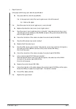
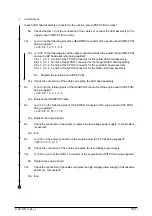
Poor Fusing (Image are blurred or peeled off when touched with finger.)
•
Is the paper under specification being used?
No
Use the paper under the specification.
▼
•
Yes
Is contacts of the fusing unit assembly connected correctly?
No
Connect the contacts correctly.
▼
•
Yes
Are there any rollers of the fusing unit (heat roller, oil roller, or cleaning oil roller) contaminated?
Yes Replace the fusing unit assembly or oil roller assembly.
▼
•
No
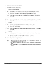
Is the setting of “MEDIA TYPE” (in menu 1)correctly?
LIGHT:60g/m
2
LIGHT MIDIUM:67.5g/m
2
MEDIUM:75g/m
2
MEDIUM HEAVY:90g/m
2
HEAVY:105g/m
2
ULTRA HEAVY:120g/m
2
TRANSPARENCY:OHP
No
Set the “MEDIA TYPE” correctly.
▼
•
Yes
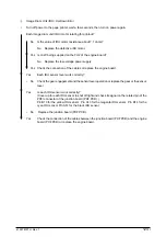
Is AC voltage between pin 1 and 3 of the CN1 connector of the low-voltage power supply
being supplied?
No
Replace the low-voltage power supply.
▼
•
Yes
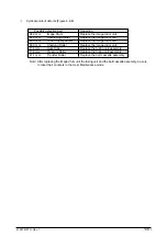
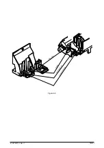
Is resistance range of the heat roller thermistor under the regulation? (See Figure 6.1.) (It's
about between 90 ohms and 700 ohms at room temperature of 0
°
C to 43
°
C)
No
Replace the fusing unit assembly.
▼
•
Yes
Is resistance range of the backup roller thermistor under the regulation? (See Figure 6.1.)
(It's about between 90 ohms and 700 ohms at room temperature of 0
°
C to 43
°
C)
No
Replace the fusing unit assembly.
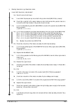
Yes Is the signal THERM1 on pin 6 of the THERM connector of the engine board (PX4 PCB) in
the following range?
LIGHT and LIGHT MEDIUM:2.8V~3.5V MEDIUM:3.1V~3.8V
MEDIUM HEAVY:3.1V~3.9V
HEAVY:3.4V~4V
ULTRA HEAVY:3.4V~4.1V
TRANSPARENCY default value:3.4V~4V
No
Replace the fusing unit assembly.
▼
•
Yes
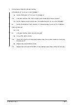
Replace the fusing unit assembly.
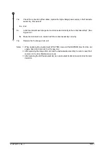
Notes: 1. When replacing the engine board (PX4 PCB), demount the EEPROM chip from the old
engine board and remount it on the new one.
2. After replacing the image drum unit, the fusing unit, and the belt cassette assembly, be sure
to reset their counters in the User Maintenance mode.
3. After replacing the LED head assembly, be sure to adjust its drive time and correct its color
deviation.
Содержание OKICOLOR 8
Страница 2: ...OKICOLOR 8 Color LED Page Printer Maintenance Manual 1999 7 14 Rev 1...
Страница 12: ...41057610TH Rev 1 11 This page intentionally left blank...
Страница 44: ...41057610TH Rev 1 43 Figure 3 1 3 2 Parts Layout...
Страница 45: ...41057610TH Rev 1 44 Figure 3 2...
Страница 46: ...41057610TH Rev 1 45 Figure 3 3...
Страница 47: ...41057610TH Rev 1 46 Figure 3 4...
Страница 105: ...41057610TH Rev 1 104 olor check pattern...
Страница 153: ...41057610TH Rev 1 152 5 PXF PCB OPTION PENDTNR TONER UPDOWN B1 A1 B15 A15 8 1 8 1 FSENS JODEN 14 1 1 12 PXFIF...
Страница 154: ...41057610TH Rev 1 153 8 Parts List Fig 8 1 4 1 5 L J 8 9 0 A H B N N M D E C G F I 7 K 3 2 P P 6 O...
Страница 156: ...41057610TH Rev 1 155 Fig 8 2 2 1 O 3 N C 0 9 Q 6 M J 8 7 8 S H E 7 K G 4 P D R L B A F T 5...
Страница 161: ...41057610TH Rev 1 160 Fig 8 4 1 6 6 6 6 5 7 4 2 2 K 2 2 3 C E 0 I C A H H H H B C F J J D G 3 3 3 8 9 9 9...
Страница 166: ...41057610TH Rev 1 165 Fig 8 6 H B E F 2 J 4 4 I 3 3 6 9 8 7 G C D A 0 5 1 5...
Страница 168: ...41057610TH Rev 1 167 Fig 8 7 1 2 5 6 3 4...
Страница 170: ...41057610TH Rev 1 169 Fig 8 8 7 7 5 A 5 6 6 3 3 4 4 0 9 1 8 2...
Страница 172: ...41057610TH Rev 1 171 Fig 8 9 7 6 6 5 5 4 1 8 8 2 3 4 3 7...
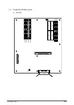
Страница 196: ...41057610TH Rev 1 195 SEN1 CN22 CN23 CN24 5 2 PCB Layout AOLT PCB...
Страница 197: ...41057610TH Rev 1 196 6 PARTS LIST 4 D 9 3 B 6 C A E F 2 J I L 0 1 K G G G 5 7 H 9 8...

