41057610TH Rev. 1
82 /
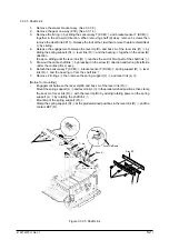
3.3.35 Shaft Link
1.
Remove the eraser bracket assy. (See 3.3.34.)
2.
Remove the gear one-way (Z30). (See 3.3.14.)
3.
Remove the E-ring
3
by sliding the sensor assy T (KCM)
1
and bracket sensor T (KCM)
2
together in the arrow (A) direction. When removing shaft (K) assy, remove 3 screws then
remove the Heat Sink-801
B
. Release the lock of the claw then remove the plate shield Heat
C
by sliding .
4.
Release the engagement between the lever Up/Dn and boss A of the lever link (R)
5
by
sliding the spring support (R)
4
, lever link (R)
5
and the bearing
6
together in the arrow (B)
direction.
(Keep on sliding until the lever link (R)
5
reaches the end of D-cut part of the shaft link
7
.)
5.
Draw out the entire shaft link
7
by pressing it in the arrow (C) direction and turning its left side
under the contact (BL L) assy.
6.
Detach the sensor assy T (KCM)
1
, bracket sensor T (KCM)
2
, spring support (R)
4
, lever
link (R)
5
and the bearing
6
from the shaft link
7
.
7.
Remove 2 E-rings
8
then remove the spring support (L)
9
and lever link (L)
0
.
[Notice for mounting]
-
Engagement between the lever Up/Dn and boss A of the lever link (R)
5
:
Mount the spring support (L)
9
and lever link (L)
0
in the predetermined positions, then clamp
the boss A of lever link (R)
5
with the lever Up/Dn by adding rotating power on the spring
support (L)
9
by rotating the shaft link
7
.
-
Mounting of the spring support (R)
4
:
Clamp the spring support (R)
4
at the predetermined positions in the lever link (R)
5
and the
contact BKT (R).
0
9
7
1
3
3
4
5
6
A
B
C
2
8
Boss A
Boss A
Stay EP
Lever Up/Down
(B)
Slide 4, 5 and 6
(A)
Slide 1, 2
(D)
Remove 7
(C)
Slide 7
Figure 3.3.35 Shaft Link
Содержание OKICOLOR 8
Страница 2: ...OKICOLOR 8 Color LED Page Printer Maintenance Manual 1999 7 14 Rev 1...
Страница 12: ...41057610TH Rev 1 11 This page intentionally left blank...
Страница 44: ...41057610TH Rev 1 43 Figure 3 1 3 2 Parts Layout...
Страница 45: ...41057610TH Rev 1 44 Figure 3 2...
Страница 46: ...41057610TH Rev 1 45 Figure 3 3...
Страница 47: ...41057610TH Rev 1 46 Figure 3 4...
Страница 105: ...41057610TH Rev 1 104 olor check pattern...
Страница 153: ...41057610TH Rev 1 152 5 PXF PCB OPTION PENDTNR TONER UPDOWN B1 A1 B15 A15 8 1 8 1 FSENS JODEN 14 1 1 12 PXFIF...
Страница 154: ...41057610TH Rev 1 153 8 Parts List Fig 8 1 4 1 5 L J 8 9 0 A H B N N M D E C G F I 7 K 3 2 P P 6 O...
Страница 156: ...41057610TH Rev 1 155 Fig 8 2 2 1 O 3 N C 0 9 Q 6 M J 8 7 8 S H E 7 K G 4 P D R L B A F T 5...
Страница 161: ...41057610TH Rev 1 160 Fig 8 4 1 6 6 6 6 5 7 4 2 2 K 2 2 3 C E 0 I C A H H H H B C F J J D G 3 3 3 8 9 9 9...
Страница 166: ...41057610TH Rev 1 165 Fig 8 6 H B E F 2 J 4 4 I 3 3 6 9 8 7 G C D A 0 5 1 5...
Страница 168: ...41057610TH Rev 1 167 Fig 8 7 1 2 5 6 3 4...
Страница 170: ...41057610TH Rev 1 169 Fig 8 8 7 7 5 A 5 6 6 3 3 4 4 0 9 1 8 2...
Страница 172: ...41057610TH Rev 1 171 Fig 8 9 7 6 6 5 5 4 1 8 8 2 3 4 3 7...
Страница 196: ...41057610TH Rev 1 195 SEN1 CN22 CN23 CN24 5 2 PCB Layout AOLT PCB...
Страница 197: ...41057610TH Rev 1 196 6 PARTS LIST 4 D 9 3 B 6 C A E F 2 J I L 0 1 K G G G 5 7 H 9 8...


