41057610TH Rev. 1
131 /
2
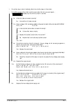
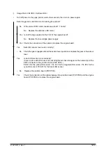
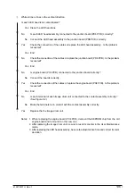
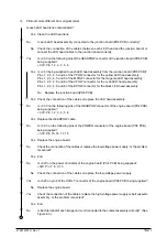
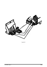
Dirty stained ground (Figure 6.2-B)
•
Each image drum exposed to external lights for a long time?
Yes Replace the image drum unit or put the image drum unit in the printer and close the upper
cover and wait for 15min.
Note: After replacing the image drum unit, be sure to reset its counter.
▼
•
No
Is the Roller of the fusing unit (heat roller, oil roller, or cleaning oil roller) contaminated?
Yes Replace the fusing unit or the oil roller assembly.
▼
•
No
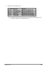
Is the setting of “MEDIA TYPE” (in menu 1) correct?
LIGHT:60g/m
2
LIGHT MIDIUM:67.5g/m
2
MEDIUM:75g/m
2
MEDIUM HEAVY:90g/m
2
HEAVY:105g/m
2
ULTRA HEAVY:120g/m
2
TRANSPARENCY:OHP
No
Set the “MEDIA TYPE” correctly.
▼
•
Yes
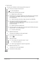
Is the setting of the LED head drive time correct?
No
Set the LED head drive time correctly.
▼
•
No
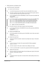
Is Each LED head assembly connected correctly to the junction board (PD6 PCB)?
No
Connect the LED assembly correctly to the junction board (PD6 PCB) correctly.
▼
•
Yes
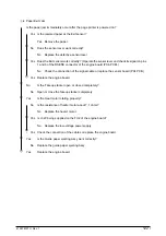
Is +3.3V on the following pins of the HEADPOW connector of the junction board (PD6 PCB)
being supplied?
+3.3V: Pin 1, 2, 3, 4, 5, 6
•
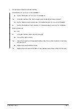
Yes Is +3.3V being supplied on the following pins of the cable connector between the junction
board (PD6 PCB) and each LED head assembly?
Pins 1, 2, 3, 4, 5 and 6 of the YPOW connector for the yellow LED head assembly
Pins 1, 2, 3, 4, 5 and6 of the MPOW connector for the magenta LED head assembly
Pins 1, 2, 3, 4, 5 and 6 of the CPOW connector for the cyan LED head assembly
Pins 1, 2, 3, 4, 5 and 6 of the BPOW connector for the black LED head assembly
No
Replace the junction board (PD6 PCB).
▼
•
Yes Check the connection of the cables or replace the LED head assembly.
▼
•
No
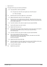
Is +3.3V on the following pins of the HEADPOW connector of the engine board (PX4 PCB)
being supplied?
+3.3V: Pin 1, 2, 3, 4, 5, 6
Yes Replace the HEADPOW cable.
▼
•
No
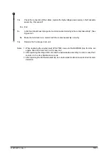
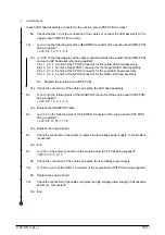
Is +3.3V on the following pins of the POWER connector of the engine board (PX4 PCB)
being supplied?
Yes Replace the engine board.
▼
•
No
Check the connection of the cables or replace the low-voltage power supply. Recovered?
Yes End
▼
•
No
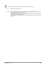
Is +32V on the power connector of the engine board (PX4 PCB) being supplied?
+32V: Pin 7, 8, 9, 10
A
Содержание OKICOLOR 8
Страница 2: ...OKICOLOR 8 Color LED Page Printer Maintenance Manual 1999 7 14 Rev 1...
Страница 12: ...41057610TH Rev 1 11 This page intentionally left blank...
Страница 44: ...41057610TH Rev 1 43 Figure 3 1 3 2 Parts Layout...
Страница 45: ...41057610TH Rev 1 44 Figure 3 2...
Страница 46: ...41057610TH Rev 1 45 Figure 3 3...
Страница 47: ...41057610TH Rev 1 46 Figure 3 4...
Страница 105: ...41057610TH Rev 1 104 olor check pattern...
Страница 153: ...41057610TH Rev 1 152 5 PXF PCB OPTION PENDTNR TONER UPDOWN B1 A1 B15 A15 8 1 8 1 FSENS JODEN 14 1 1 12 PXFIF...
Страница 154: ...41057610TH Rev 1 153 8 Parts List Fig 8 1 4 1 5 L J 8 9 0 A H B N N M D E C G F I 7 K 3 2 P P 6 O...
Страница 156: ...41057610TH Rev 1 155 Fig 8 2 2 1 O 3 N C 0 9 Q 6 M J 8 7 8 S H E 7 K G 4 P D R L B A F T 5...
Страница 161: ...41057610TH Rev 1 160 Fig 8 4 1 6 6 6 6 5 7 4 2 2 K 2 2 3 C E 0 I C A H H H H B C F J J D G 3 3 3 8 9 9 9...
Страница 166: ...41057610TH Rev 1 165 Fig 8 6 H B E F 2 J 4 4 I 3 3 6 9 8 7 G C D A 0 5 1 5...
Страница 168: ...41057610TH Rev 1 167 Fig 8 7 1 2 5 6 3 4...
Страница 170: ...41057610TH Rev 1 169 Fig 8 8 7 7 5 A 5 6 6 3 3 4 4 0 9 1 8 2...
Страница 172: ...41057610TH Rev 1 171 Fig 8 9 7 6 6 5 5 4 1 8 8 2 3 4 3 7...
Страница 196: ...41057610TH Rev 1 195 SEN1 CN22 CN23 CN24 5 2 PCB Layout AOLT PCB...
Страница 197: ...41057610TH Rev 1 196 6 PARTS LIST 4 D 9 3 B 6 C A E F 2 J I L 0 1 K G G G 5 7 H 9 8...

