41057610TH Rev. 1
93 /
4.
ADJUSTMENTS
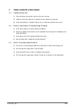
Adjustments are carried out by key operations on the operator panel, by software operation panel,
and by EEPROM of PU (PX4-PCB) setting.
This page printer supports three maintenance modes. Select and set a maintenance mode fit for
the adjustment.
4.1
Maintenance Modes and Their Functions
4.1.1
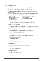
User maintenance mode
To set the user maintenance mode, turn on the power switch of the page printer while pressing on
the MENU key.
•
Functions
-
Menu reset
-
Hex dump
-
Resource save area
-
Receive buffer size
-
Operator panel menu disable
-
X adjust
-
Y adjust
(a) Menu reset
1
Resets all Menu Level 1 settings to the default settings (which have been factory-set).
2
Resets all executable Emulation menu items (including options) to factory-set default
emulation items.
(b) Hex dump
1
Receives data from the host computer and dumps it in a hexadecimal format.
2
When one page of data or more comes from the host, printing automatically starts.
To print out data of less than one page, press the ONLINE key to set the offline state
and press the EJECT key. Printing starts.
3
To exit this mode, shut off power to the page printer.
(This is the only one way to exit this mode.)
(c) Resource save area
Sets the resource saving area. This menu item appears when the option PS SIMM and
RAM increases, the selectable size will also increase (When adding a RAM over
24Mbytes, the selection can be made up to 22.5Mbytes). The size upon auto will also
increase if the size of the add-on RAM increases.
(d) Receive buffer
Sets the receive buffer. The data transmission time from the upper command will
decrease when set to a high value, but memory overflow will occur easier. Memory will
be restructured with this change, and the contents of all download fonts, PCL macro, and
PodtScript will be lost.
(e) Operator panel menu disable
Enables or disables the menu functions (Menu1, Menu2, Tray Type, Power Save, and
Paper Size) of the operator panel.
(f) X adjust
1
Corrects the position of the whole print image so that it may be perpendicular to the
movement of paper (at intervals of 0.25mm).
2
The print image exceeding the specified printable area is clipped.
(g) Y adjust
1
Corrects the position of the whole print image so that it may be parallel to the
movement of paper (at intervals of 0.25mm).
2
The print image exceeding the specified printable area is clipped.
Содержание OKICOLOR 8
Страница 2: ...OKICOLOR 8 Color LED Page Printer Maintenance Manual 1999 7 14 Rev 1...
Страница 12: ...41057610TH Rev 1 11 This page intentionally left blank...
Страница 44: ...41057610TH Rev 1 43 Figure 3 1 3 2 Parts Layout...
Страница 45: ...41057610TH Rev 1 44 Figure 3 2...
Страница 46: ...41057610TH Rev 1 45 Figure 3 3...
Страница 47: ...41057610TH Rev 1 46 Figure 3 4...
Страница 105: ...41057610TH Rev 1 104 olor check pattern...
Страница 153: ...41057610TH Rev 1 152 5 PXF PCB OPTION PENDTNR TONER UPDOWN B1 A1 B15 A15 8 1 8 1 FSENS JODEN 14 1 1 12 PXFIF...
Страница 154: ...41057610TH Rev 1 153 8 Parts List Fig 8 1 4 1 5 L J 8 9 0 A H B N N M D E C G F I 7 K 3 2 P P 6 O...
Страница 156: ...41057610TH Rev 1 155 Fig 8 2 2 1 O 3 N C 0 9 Q 6 M J 8 7 8 S H E 7 K G 4 P D R L B A F T 5...
Страница 161: ...41057610TH Rev 1 160 Fig 8 4 1 6 6 6 6 5 7 4 2 2 K 2 2 3 C E 0 I C A H H H H B C F J J D G 3 3 3 8 9 9 9...
Страница 166: ...41057610TH Rev 1 165 Fig 8 6 H B E F 2 J 4 4 I 3 3 6 9 8 7 G C D A 0 5 1 5...
Страница 168: ...41057610TH Rev 1 167 Fig 8 7 1 2 5 6 3 4...
Страница 170: ...41057610TH Rev 1 169 Fig 8 8 7 7 5 A 5 6 6 3 3 4 4 0 9 1 8 2...
Страница 172: ...41057610TH Rev 1 171 Fig 8 9 7 6 6 5 5 4 1 8 8 2 3 4 3 7...
Страница 196: ...41057610TH Rev 1 195 SEN1 CN22 CN23 CN24 5 2 PCB Layout AOLT PCB...
Страница 197: ...41057610TH Rev 1 196 6 PARTS LIST 4 D 9 3 B 6 C A E F 2 J I L 0 1 K G G G 5 7 H 9 8...

