


4.5.3 Linux PTP stack
The Linux PTP stack software is an implementation of the Precision Time Protocol (PTP) based on the IEEE standard 1588 for
Linux. Its dual design goals are:
• To provide a robust implementation of the standard.
• To use the most relevant and modern Application Programming Interfaces (API) offered by the Linux kernel.
Supporting legacy APIs and other platforms is not an objective of this software. Following are the main features of the Linux PTP
stack:
• Supports hardware and software time stamping via the Linux SO_TIMESTAMPING socket option.
• Supports the Linux PTP Hardware Clock (PHC) subsystem by using the clock_gettime family of calls, including the new
clock_adjtimex system call.
• Implements Boundary Clock (BC) and Ordinary Clock (OC).
• Transport over UDP/IPv4, UDP/IPv6, and raw Ethernet (Layer 2).
• Supports IEEE 802.1AS-2011 in the role of end station.
• Modular design allows painless addition of new transports and clock servo algorithms.
4.5.4 Quick start guide for setting up IEEE standard 1588 demonstration
This quick start guide explains the procedure to set up demos of IEEE 1588, including master-slave synchronization, boundary
clock synchronization, and transparent clock synchronization.
1. Hardware requirement
• Two boards for basic master-slave synchronization
• Three or more boards for BC synchronization
• Three or more boards for TC synchronization (One must be LS1021ATSN board)
2. Software requirement
• Linux BSP of industry solution release
• PTP software stack
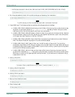
3. Ethernet interfaces connection for master-slave synchronization
Connect two Ethernet interfaces between two boards in a back-to-back manner. Then, one board works as master and
the other works as a slave when they synchronize. Both the master and the slave work as Ordinary Clocks (OCs).
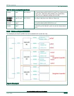
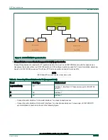
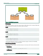
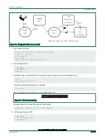
4. Ethernet interfaces connection for BC synchronization
At least three boards are required for BC synchronization. When three boards are used for BC synchronization, assuming
board A works as boundary clock (BC) with two PTP ports, board B and board C work as OCs.
Table 19. Connecting Ethernet interfaces for boundary clocks (BC) synchronization
Board
Clock type
Interfaces used
A
BC
Interface 1, Interface 2.
B
OC
Interface 1
C
OC
Interface 1
5. Connect board A interface 1 to board B interface 1 in back-to-back manner.
6. Connect board A interface 2 to board C interface 1 in back-to-back manner. For example, LS1021ATSN BC synchronization
connection is shown in the following figure.
NXP Semiconductors
Industrial features
Open Industrial User Guide, Rev. 1.8, 05/2020
User's Guide
49 / 199