


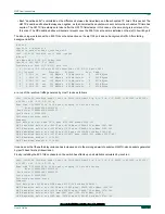


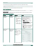


• Because the default (implicit) summary_interval in /etc/linuxptp.cfg is 0 (print stats once per second) and the logSyncInterval
required by 802.1AS is -3 (the sync messages are sent at an interval of 1/8 seconds - 125 ms), this means that synchronization
stats cannot be printed in full (for each packet) and are printed in an abbreviated form (there is no "offset" in the logs).
• The offset to the master has a root mean square value of 9 ms, with a maximum of 15 ns in the past 1 second.
• The frequency correction required to synchronize to the GM was on average -19750 parts per billion (ppb). If the frequency
adjustment exceeds a certail sanity threshold (depending on kernel driver), ptp4l may print "clockcheck" warnings and stop
synchronization. This can be sometimes remedied manually by running the following command to reset the PTP clock
frequency adjustment to zero:
phc_ctl /dev/ptp0 freq 0
• The measured path delay (MAC to MAC propagation delay for ~70 bytes frames at 1Gbps) between its device and its link
partner is exactly 736 ns.
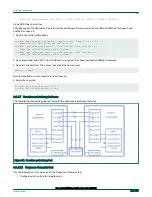
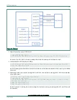
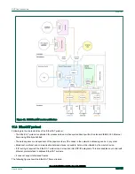
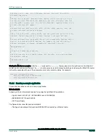
The clock distribution tree in this network is as follows: the system clock of the PTP GM (e.g. Host 1) disciplines its PTP hardware
clock (/dev/ptp0), using phc2sys. Over Ethernet, the PTP GM disciplines the SJA1105 PHC, which disciplines the PTP slave (e.g.
Host 2). On the slave host, the phc2sys process runs in the reverse direction, disciplining the system clock (CLOCK_REALTIME)
to the PTP hardware clock (/dev/ptp0).
A note on using the LS1021A-TSN board as a gPTP GM for this scenario (in place of Host 1). On this board there is no battery-
backed RTC, so there is no persistent source of time onboard. One has to rely on the NTP service (ntpd.service) to provide time,
otherwise a time in 1970 will be relayed into the PTP network.
A note on using phc2sys on the slave host. Since phc2sys attempts to discipline CLOCK_REALTIME, one must manually ensure
that other daemons in the system do not attempt to do the same thing, such as ntpd. Otherwise there will be access conflicts
between phc2sys and the other daemon, and phc2sys will keep printing clockcheck warning messages.
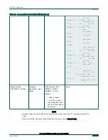
Install the following schedule into the sja1105 port egressing towards Host 2:
tc qdisc add dev swp2 parent root taprio \
num_tc 8 \
map 0 1 2 3 4 5 6 7 \
queues 1@0 1@1 1@2 1@3 1@4 1@5 1@6 1@7 \
base-time 0 \
sched-entry S 80 50000 \
sched-entry S 40 50000 \
sched-entry S 3f 300000 \
flags 2
The base-time of 0 indicates the phase offset of the network schedule. This time corresponds to Jan 1st 1970, but it is automatically
advanced into an equivalent time into the immediate PTP future (it is advanced by an integer number of cycle-time nanoseconds).
The cycle-time in this example is not provided explicitly, but it is calculated as the sum of the durations of all gate events: 400
microseconds (us).
The schedule at the egress of swp2 is divided as follows:
• 50 us for PTP traffic (S 80). The traffic class assignment of 7 for link-local management traffic (STP, PTP, etc) is fixed to 7
at driver level and is not user configurable at this time.
• 50 us for traffic class 6 (S 40). The latency-sensitive traffic generator will be injecting into this window.
• 300 us for all other traffic classes 0-5 (S 3f).
Enabling QoS classification on the sja1105 switch based on VLAN PCP is done by running:
ip link set dev br0 type bridge vlan_filtering 1
NXP Semiconductors
TSN
Open Industrial User Guide, Rev. 1.8, 05/2020
User's Guide
136 / 199