


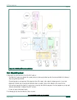


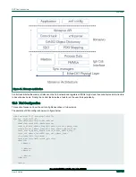


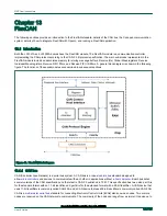


Figure 47. Libnservo architecture
Control task initiates the master, all slaves on the CoE network and registers all PDOs to Igh stack, then constructs a data structure
to describe each axle. Finally, the control task creates a task to run the user task periodically.
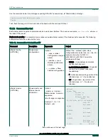
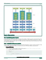
12.3 Xml Configuration
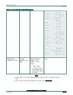
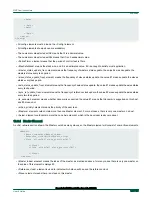
This section focuses on how the xml config file describes a CoE network.
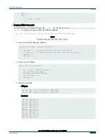
The skeleton of XML config is shown as in figure below:
<?xml version="1.0" encoding="utf-8"?>
<Config Version="1.2">
<PeriodTime>#10000000</PeriodTime>
<MaxSafeStack>#8192</MaxSafeStack>
<master_status_update_freq>#1</master_status_update_freq>
<slave_status_update_freq>#1</slave_status_update_freq>
<axle_status_update_freq>#1</axle_status_update_freq>
<sync_ref_update_freq>#2</sync_ref_update_freq>
<is_xenomai>#1</is_xenomai>
<sched_priority>#82</sched_priority>
<Masters>
<Master>
...
<\Master>
<Master>
...
<\Master>
<\Master>
<Axles>
NXP Semiconductors
nxp-servo
Open Industrial User Guide, Rev. 1.8, 05/2020
User's Guide
156 / 199