


CANopen provides several communication objects, which enable device designers to implement desired network behavior into
a device. With these communication objects, device designers can offer devices that can communicate process data, indicate
device-internal error conditions or influence and control the network behavior. As CANopen defines the internal device structure,
the system designer knows exactly how to access a CANopen device and how to adjust the intended device behavior.
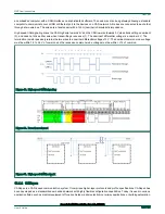
• CANopen lower layers
CANopen is based on a data link layer according to ISO 11898-1. The CANopen bit timing is specified in CiA 301 and allows
the adjustment of data rates from 10 kbit/s to 1000 kbit/s. Although all specified CAN-ID addressing schemata are based on
the 11-bit CAN-ID, CANopen supports the 29-bit CAN-ID as well. Nevertheless, CANopen does not exclude other physical
layer options.
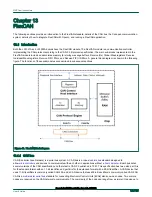
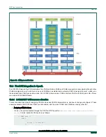
• Internal device architecture
A CANopen device consists of three logical parts. The CANopen protocol stack handles the communication via the CAN
network. The application software provides the internal control functionality. The CANopen object dictionary interfaces the
protocol as well as the application software. It contains indices for all used data types and stores all communication and
application parameters. The CANopen object dictionary is most important for CANopen device configuration and diagnostics.
• CANopen protocols
— SDO protocol
— PDO protocol
— NMT protocol
— Special function protocols
— Error control protocols
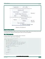
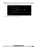
The following figure shows the CANopen architecture.
NXP Semiconductors
FlexCAN
Open Industrial User Guide, Rev. 1.8, 05/2020
User's Guide
166 / 199