


Chapter 3
Hardware Overview
3-16
ni.com
Both the source and the destination of an asynchronous routing operation
on the NI 6653 can be any of the following lines:
•
Any front panel PFI pin (PFI <0..5)
•
Any PXI star trigger line (PXI_STAR<0..12>)
•
Any PXI/RTSI trigger line (PXI_TRIG<0..7>)
Synchronous Routing
A synchronous routing operation is defined in terms of three signal
locations: A source, a destination, and
synchronization clock
. A digital
signal comes in on the source and is propagated to the destination after the
edge has been realigned with the synchronization clock.
Unlike asynchronous routing, the output of a synchronous routing
operation does not directly follow the input after a propagation delay.
Instead, the output waits for the next rising edge of the clock before it
follows the input. Thus, the output is said to be “synchronous” with this
clock.
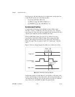
Figure 3-6 shows a timing diagram that illustrates synchronous routing.
Figure 3-6.
Synchronous Routing Operation
Synchronous routing can send triggers to several places in the same clock
cycle or send the trigger to those same places after a deterministic skew of
a known number of clock cycles. If a signal arrives at two chassis within the
same clock cycle, each NI 6653 realigns the signal with the
Trigger Input
Synchronization
Clock
Trigger Output
Setup
Time
t
setup
Hold
Time
t
hold
Clock to Output
Time, t
CtoQ


