


Chapter 3
Hardware Overview
©
National Instruments Corporation
3-5
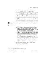
Table 3-2 illustrates the meaning of each Active LED color.
Note
A red Active LED can indicate that either PXI_CLK10 has stopped
or
that there is
a PLL error.
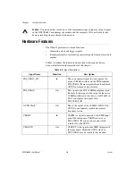
Connectors
This section describes the connectors on the front panel of the NI 6653.
•
CLKIN
1
—Clock Input. This connector supplies the module with a
clock that can be programmatically routed to the onboard PLL for use
as a reference or routed directly to the PXI backplane
(PXI_CLK10_IN) for distribution to the other modules in the chassis.
•
CLKOUT
1
—Clock Output. This connector is used to source a clock
that can programmatically be routed from the oven-controlled crystal
oscillator (OCXO), Direct Digital Synthesis (DDS), or backplane
clock (PXI_CLK10).
•
PFI <0..5>
—Programmable Function Interface <0..5>. These
connectors can be used for either input or output. Additionally,
PFI 0
can be used as a clock input for internally synchronizing other signals.
Refer to the
section for more information about
this functionality
.
You can program the behavior of these PFI
connections individually.
Refer to Figure 3-2 for a diagram showing the locations of these
connections on the NI 6653 front panel.
Table 3-2.
Active LED Color Quick Reference Table
Color
PXI_CLK10
Stopped
PLL
Error
1
User
Setting
1
PLL
Active
1
Red
Yes
Yes
—
—
Amber
—
—
Yes
—
Green
—
—
—
Yes
Off
—
—
—
—
1
This feature is not supported in version 1.0 of the NI 6653 Driver Software
1
This feature is not supported in version 1.0 of the NI 6653 Driver Software.


