2-14 General Description
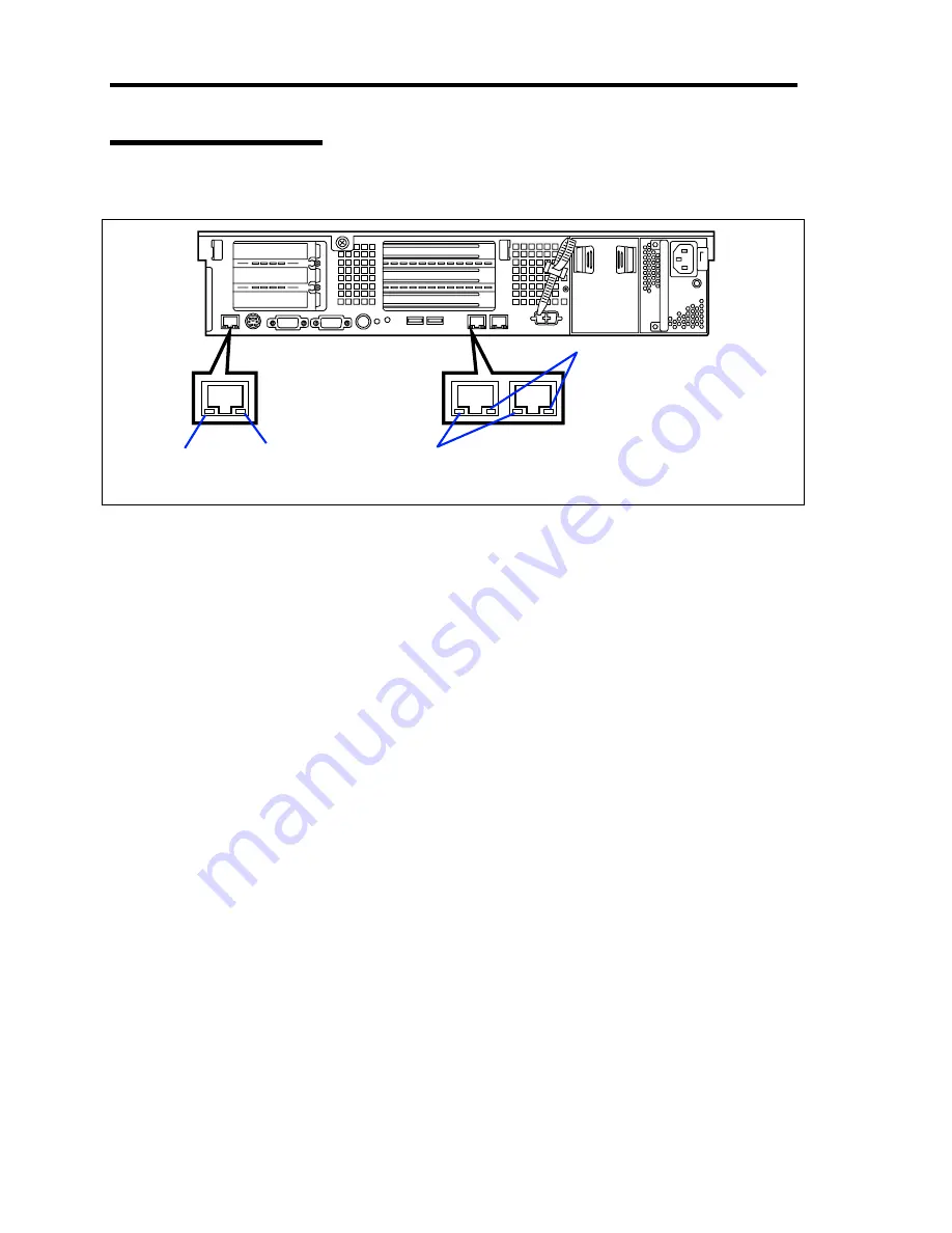
LAN Connector LEDs
There are two LEDs for each of the three LAN ports (connectors) on the rear panel.
LINK/ACT LEDs
Each LINK/ACT LED indicates the status of the standard network port of the server.
While power is supplied to the server and HUB and the connection is correct, the LED is
on (green). The LED turns green and flashes while the network port is
transmitting/receiving data.
If the LED does not go on when the LINK state is placed, check if the network cable is in
normal state and if it is connected correctly. If the LED does not go on yet when the
network cable is normal, the network (LAN) controller may be faulty. In this case, contact
your service representative.
Speed LEDs (for data transmission ports)
This LED indicates whether each of the network ports normally equipped with the server
is operated through the 1000BASE-T, 100BASE-TX or 10BASE-T network interface. If
the LED is lit amber, the network port is operated through 1000BASE-T. If the LED is lit
green, the network port is operated through 100BASE-TX. If the LED is off, the network
port is operated through 10BASE-T.
Speed LED (for management port)
This LED indicates whether each of the network ports normally equipped with the server
is operated through the 100BASE-TX or 10BASE-T network interface. If the LED is lit
amber, the network port is operated through 100BASE-TX. If the LED is off, the network
port is operated through 10BASE-T.
Speed LEDs
LINK/ACT LEDs
Management port
Data transmission ports
Speed LEDs
LINK/ACT LEDs
Содержание Express5800/120Rj-2
Страница 16: ...x This page is intentionally left blank ...
Страница 19: ...Notes on Using Your Server 1 3 Internal View ...
Страница 34: ...1 18 Notes on Using Your Server This page is intentionally left blank ...
Страница 90: ...3 24 Setting Up Your Server This page is intentionally left blank ...
Страница 129: ...Configuring Your Server 4 39 The detailed settings is continued to the next page Click Next to view more information ...
Страница 140: ...4 50 Configuring Your Server Use this menu to define several physical drives PD as a disk group DG ...
Страница 164: ...4 74 Configuring Your Server 3 Setting menu for VD 0 is displayed ...
Страница 172: ...4 82 Configuring Your Server This page is intentionally left blank ...
Страница 215: ...Installing and Using Utilities 6 9 4 Click Parameter File Creator Parameter File Creator will appear ...
Страница 240: ...7 12 Maintenance This page is intentionally left blank ...
Страница 350: ...9 74 Upgrading Your Server Removal Remove the backup device in reverse order of the installation steps ...
Страница 354: ...9 78 Upgrading Your Server This page is intentionally left blank ...
Страница 364: ...C 2 IRQ This page is intentionally left blank ...
Страница 412: ...E 24 Installing Windows Server 2003 This page is intentionally left blank ...
Страница 414: ...F 2 Using a Client Computer Which Has a CD Drive This page is intentionally left blank ...
Страница 418: ...G 4 Product Configuration Record Table This page is intentionally left blank ...


