


2-10
Setting Up the System
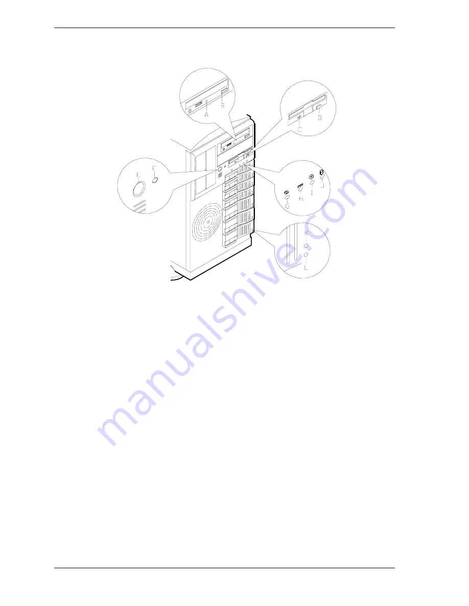
This figure shows the location of the front system controls and indicators.
A
– Activity light, CD-ROM reader
When lit, CD-ROM reader is in use.
B
– Load/eject button, CD-ROM reader
Press to load CD and eject CD.
C
– Activity light, 3 ½-inch diskette drive
When lit, diskette is in use.
D
– Eject button, 3 ½-inch diskette drive
Press to eject diskette.
E
– DC power ON/OFF switch
Press to turn system DC power on or off.
F
– Reset switch
Press to reinitialize system.
G
– DC power ON/OFF LED
See table "Front System Status Indicator LEDs" that follow.
H
– Power alarm
See table "Front System Status Indicator LEDs" that follow.
I
– Fan alarm
See table "Front System Status Indicator LEDs" that follow.
J
– Array alarm
See table "Front System Status Indicator LEDs" that follow.
K
– Disk drive status LED
See table "Front System Status Indicator LEDs" that follow.
L
– Disk drive activity LED
See table "Front System Status Indicator LEDs" that follow.
Front System Features and Controls
Содержание Express5800/120Mc2 series
Страница 1: ... U s e r s G u i d e EXPRESS5800 120Mc2 ...
Страница 2: ...xxx ...
Страница 3: ... U s e r s G u i d e EXPRESS5800 120Mc2 ...
Страница 50: ...2 18 Setting Up the System ...
Страница 106: ...4 34 Upgrading Your System Plugging in the AC Power Cords ...
Страница 125: ...A System Cabling System Cabling Before You Begin Static Precautions Standard Configuration RAID Configuration ...
Страница 129: ...System Cabling A 5 A Ultra 160 M SCSI cable 68 pins B IDE cable 40 pins Standard System Cable Routing ...
Страница 132: ...A 8 System Cabling A Ultra 160 M SCSI cable 68 pins B IDE cable 40 pins RAID System Cable Routing ...
Страница 154: ...B 22 Management Workstation Application ...
Страница 155: ...C System Status Hardware Support Information ...
Страница 166: ...10 Glossary ...
Страница 171: ...xx ...
Страница 172: ... 456 01524 000 ...


