background image

4-10


Upgrading Your System

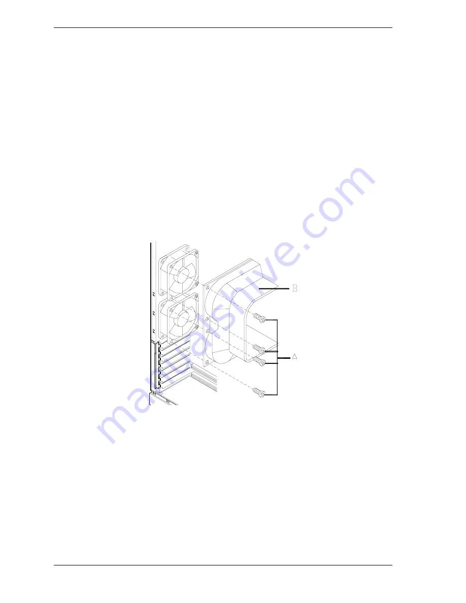
Removing and Installing the Cooling Baffle

If your system has a cooling baffle, remove and install it as follows.

1. 

Remove the cooling baffle as follows.

!


Locate the two fans inside the chassis, at the rear of the chassis.

!


Remove four screws (two from each fan) from the fans, as shown in the
following figure.

!


Remove the baffle.

2. 

Install the cooling baffle as follows.

!


Align the baffle mounting holes with the fan mounting holes.

!


Fasten the baffle in place with the four fan mounting screws.

!


Replace the left side panel, plug in the power cords, and power up the
system.

A

 – Screws

B

 – Baffle

Removing and Installing the Cooling Baffle

Содержание Express5800/120Mc2 series

Страница 1: ... U s e r s G u i d e EXPRESS5800 120Mc2 ...

Страница 2: ...xxx ...

Страница 3: ... U s e r s G u i d e EXPRESS5800 120Mc2 ...

Страница 4: ... system configuration customer data and operator control Since implementation by customers of each product may vary the suitability of specific product configurations and applications must be determined by the customer and is not warranted by NEC CSD To allow for design and specification improvements the information in this document is subject to change at any time without notice Reproduction of t...

Страница 5: ...em Board Management Controller BMC 1 16 ACPI 1 17 AC Link Mode 1 17 Remote Power On Wake On LAN Function 1 18 System Security 1 18 Security with Mechanical Locks and Monitoring 1 18 Software Locks via the BIOS Setup Utility 1 18 2 Setting Up the System Overview 2 2 Selecting a Site 2 2 Unpacking the System 2 3 Rack Mount Subsystem Assembly 2 4 Before You Begin 2 4 Static Precautions 2 4 Assembly 2...

Страница 6: ... SCSI Utility 3 16 Adaptec SCSI Utility Configuration Settings 3 17 Exiting Adaptec SCSI Utility 3 18 Configuring the RAID Controller 3 19 Configuring System Board Jumpers 3 20 Before You Begin 3 20 Moving System Board Jumpers 3 21 Clearing and Changing the Passwords 3 22 4 Upgrading Your System General Information 4 2 Static Precautions 4 2 Preparing Your System for Upgrade 4 3 Equipment Log 4 3 ...

Страница 7: ...roper Operation of Key System Indicators 5 8 Confirming Loading of the Operating System 5 8 Specific Problems and Corrective Actions 5 9 Power LED Does Not Light 5 9 Incorrect or No Beep Code 5 10 No Characters Appear on Screen 5 10 Characters are Distorted or Incorrect 5 11 System Cooling Fans Do Not Rotate 5 11 Diskette Drive Activity LED Does Not Light 5 11 CD ROM Drive Activity Light Does Not ...

Страница 8: ... and Disconnecting the Server B 12 Using a Remote Drive B 13 Setting and Clearing Server Pause B 13 Recovering from an SOS B 14 Alerting ESMPROTM B 15 Dialog Boxes B 15 Select a Server Dialog Box B 15 Server Properties Dialog Box B 15 Default Server Properties Dialog Box B 16 Create Copy FD Image File Dialog Box B 17 Server Summary Dialog Box B 17 Delete Logged Messages Dialog Box B 17 Data Dialog...

Страница 9: ...s chapter also provides information on system board jumper settings Chapter 4 Upgrades and Options provides you with instructions for upgrading your system with an additional processor optional memory options cards peripheral devices and redundant power supply Chapter 5 Problem Solving contains helpful information for solving problems that might occur with your system Appendix A System Cabling inc...

Страница 10: ...loss of life CAUTION Cautions indicate situations that can damage the system hardware or software Note Notes give important information about the material being described Names of keyboard keys are printed as they appear on the keyboard For example Ctrl Alt or Enter Text or keystrokes that you enter appear as boldface type For example type abc123 and press ENTER File names are printed in uppercase...

Страница 11: ...veloped and released Getting Started Sheet The Getting Started Sheet provides several easy to follow steps to become familiar with your server documentation and to complete your installation successfully Network Operating System Configuration Guide This guide contains supplemental instructions needed to install and configure your server Windows NT 4 0 Novell NetWare v5 0 Santa Cruz Operation SCO O...

Страница 12: ...doing the procedures in this manual make sure that your system is powered off and unplug the AC power cords from the back of the chassis Failure to disconnect power before opening your system can result in personal injury and equipment damage In the U S A and Canada the power cord must be a UL listed detachable power cord in Canada CSA certified type ST or SJT 16 AWG 3 conductor provided with a mo...

Страница 13: ...the external ports Remote Earths To prevent electrical shock connect all local individual office computers and computer support equipment to the same electrical circuit of the building wiring If you are unsure check the building wiring to avoid remote earth conditions Earth Bonding For safe operation only connect the equipment to a building supply that is in accordance with current wiring regulati...

Страница 14: ...system warm or cool to room temperature before using it Keep the system away from magnetic forces Keep the system dry Do not wash the system with a wet cloth or pour fluid into it Protect the system from being bumped or dropped Check the system for condensation If condensation exists allow it to evaporate before powering on the system Keep the system away from dust sand and dirt ...

Страница 15: ...stem Overview Overview System Chassis Power Supply Peripheral Bays SAF TE SCSI Accessed Fault Tolerant Enclosure Board System Board Features AC Link Mode Remote Power On Wake On LAN Function System Security ...

Страница 16: ...high performance environment for many server market applications These range from large corporations supporting remote offices to small companies looking to obtain basic connectivity capability such as file and print services e mail web access web site server etc This server is also conveniently housed and available as a tower based system or as a rack mount system fits into a standard EIA 19 inch...

Страница 17: ...r supply units that can be easily installed or removed from the back of the chassis without turning the system power off SCSI drive bays accessible from the front of the chassis Hot swap SCSI disk drive backplane a failed drive can be removed and replaced with a new drive without system power being turned off if an optional Redundant Array of Independent Disks RAID controller is installed High deg...

Страница 18: ...hanced IDE controller Chassis that holds up to 12 drives seven hot swap bays for Ultra 160 M SCSI hard drives four media bays with a CD ROM installed and a 3 5 inch bay with a diskette drive Seven hot swap SCSI hard disk drive bays accessible from the front of the chassis The bays are secured behind a lockable front door tower version only where the drives can be swapped in or out of the system wi...

Страница 19: ...structure The major system components are shown in the following illustrations A Removable media bays 2 E Rear exhaust fans B Speaker Switch assembly F Interlock switch Side Covers C System board D Front input fan G Intrusion switch Front Cover Tower version only System Chassis Left Side View ...

Страница 20: ...F TE board J Power supply module slots one standard power supply slot and one optional power supply slot E SCSI disk drive bays 7 K Power supply status LED F SCSI backplane board L DC power LED G Fans behind SCSI disk drive bays 3 standard fans M Power available switch N Power supply distribution board System Chassis Right Side View ...

Страница 21: ...OM drive and optional tape drives etc Seven hot swap SCSI hard disk drive bays for mounting up to seven SCSI hard disk drives in easily removable drive carriers Note The SCSI hard disk drive bays contain a hot swap back plane that require an 80 pin single connector attachment SCA connector on the drives that you install SAF TE Board The system has a SAF TE SCSI Accessed Fault Tolerant Enclosure bo...

Страница 22: ... in boards F Not used W 64 bit 33 MHz PCI slot for add in board G Not used X 32 bit 33 MHz PCI slots for add in boards H Power on off switch connector Y PCI ISA shared slot for add in board I Not used Z Fan connectors Fan1 Fan2 J Main power connector AA LAN RJ 45 network controller connector K Reset switch connector BB SVGA monitor port connector L Speaker connector CC Parallel port connector M Di...

Страница 23: ...aximum of 133 MHz The second level cache is located on the substrate of the processor cartridge The cache includes burst pipelined synchronous static RAM BSRAM System Memory The system board contains four 168 pin DIMM sockets Memory is partitioned as four banks of registered SDRAM DIMMs PC133 compatible each providing 72 bits of noninterleaved memory 64 bit main memory plus ECC Your system may inc...

Страница 24: ...figure The top two PCI connector slots PCI 1 and PCI 2 support bus speeds up to 66 MHz The third connector slot PCI 3 only supports a bus speed of up to 33 MHz Note The bus speed for the two 66 MHz PCI connector slots PCI 1 or PCI 2 is decreased to 33 MHz if a PCI card is installed into connector slot PCI 3 or if a 33 MHz PCI card is installed into any one of the two 66 MHz PCI connector slots PCI...

Страница 25: ... shares a chassis connector slot with an ISA connector ISA 1 PCI features Bus speed up to 33 MHz 32 bit memory addressing 5 V signaling environment Burst transfers up to a peak of 132 MB s 8 16 or 32 bit data transfers Plug and Play ready Parity enabled Note If a 33 MHz PCI card is installed into one of the 66 MHz PCI slots the bus speed for the 66 MHz PCI slots is decreased to 33 MHz ...

Страница 26: ...rd has one full length ISA connector A as shown in the following figure The ISA connector ISA 1 shares a chassis connector slot with a PCI connector PCI 7 ISA features Bus speed up to 8 33 MHz 16 bit memory addressing 8 or 16 bit data transfers Plug and Play ready ...

Страница 27: ...mber of security reliability and management features also have been incorporated to meet vital server needs IDE Controller The system includes a single channel enhanced IDE 32 bit interface controller for intelligent disk drives with disk controller electronics onboard The controller has a connector located on the system board that supports a master and a slave device The IDE controller provides s...

Страница 28: ...t and autoswitching for 10 or 100 Mbps network speeds Support for both 10 Mbps and 100 Mbps networks capable of full or half duplex with back to back transmit at 100 Mbps Support for Wake On LAN SCSI Controller The system board includes an embedded Adaptec AIC7899 dual function SCSI controller The AIC7899 provides Ultra 160 M and Wide Ultra2 SCSI interfaces as two independent PCI functions As impl...

Страница 29: ...t can be programmed to generate edge or level sensitive interrupts When disabled serial port interrupts are available to add in boards Parallel Port One IEEE 1284 compatible 25 pin bidirectional EPP supporting levels 1 7 and 1 9 parallel port is provided BIOS programming enables the parallel port and determines the port address and interrupt ECP mode is supported with 2 possible DMA channels When ...

Страница 30: ...urrence in the nonvolatile System Event Log SEL The events being monitored include overtemperature and overvoltage conditions fan failure or chassis intrusion To enable accurate monitoring the BMC maintains the nonvolatile Sensor Data Record SDR from which sensor information can be retrieved The BMC provides an ISA host interface to SDR sensor information so that software running on the server can...

Страница 31: ... AC power is disconnected is the system completely off The sleep states are defined as follows s0 Normal running state s1 Processor sleep state No context will be lost in this state and the processor caches will maintain coherency s4 Hibernate or Save to Disk The memory and machine state are saved to disk Pressing the power button or other wakeup event restores the system state from the disk and r...

Страница 32: ...computer chassis includes an intrusion switch for the front cover and interlock switches for both the left side and the right side covers as viewed from the front When the intrusion switch is opened the switch transmits an alarm signal to the system board where server management software processes the signal The side cover switches operate as interlock switches controlling power shut down to the s...

Страница 33: ...he System Overview Selecting a Site Unpacking the System Rack Mount Subsystem Assembly Getting Familiar with the System Making Connections Setting the Line Voltage Connecting the Power Cord s Powering On Your System ...

Страница 34: ...wer service connection is through a properly grounded outlet CAUTION When two power supplies are installed in the system the power plug from each of the power supplies must be plugged into the same common ground power outlets Clean dust free and well ventilated Front and rear ventilating openings kept free of obstructions Away from sources of heat vibration or physical shock Isolated from strong e...

Страница 35: ...o avoid personal injury make sure you have someone help you lift or move the system When you receive your system if the shipping boxes are damaged note the damage and if possible photograph it for reference After removing the contents of the containers keep the cartons and the packing materials If the contents appear damaged when you unpack the boxes file a damage claim with the carrier immediatel...

Страница 36: ... other than those specified in the procedure Do not touch I O connector pins All screws are phillips head unless otherwise specified On completion of any assembly or reassembly perform a power on test If a fault occurs verify that the assembly or reassembly was performed correctly If the problem persists see Problem Solving in Chapter 5 Static Precautions An electrostatic discharge ESD can damage ...

Страница 37: ...inet you should consider the length of the cables that interconnect system components 2 Locate the two support brackets D Using four self tapping screws E supplied with the rack cabinet for each support bracket attach the two support brackets to the vertical mounting rails A and B of the rack cabinet 3 Install the four caged nuts C that secure the front of the rack mount server unit to the rack ca...

Страница 38: ... Setting Up the System A Rear vertical mounting rail D Two support brackets B Front vertical mounting rail E Eight self tapping screws C Four caged nuts Assembling the Support Brackets in the Rack Cabinet ...

Страница 39: ... lifting and assembling the rack mount server unit into a rack cabinet 5 Secure the front bezel to the rack cabinet s front vertical mounting rails B using the four screws E and plastic washers D provided with the rack cabinet A Rear vertical mounting rail D Four plastic washers B Front vertical mounting rail E Four screws C Rack mount server unit Installing the Rack Mount Server Unit into the Rac...

Страница 40: ...at this section describes the tower based system controls switches and indicators and connectors which are identical for the rack mount system Front View with Front Door Closed This figure shows the location of the front system features tower based system only A System indicators See Front View with Front Door Opened later in this chapter B Keylock When locked secures the front door not allowing a...

Страница 41: ...t door of the cabinet as follows tower based system only 1 If door is locked unlock the front door 2 Pull the bottom of the front door out and tilt up until it is aligned level with the top of the cabinet then push the door back directly over the top of the cabinet as far as it will go Opening the Front Door ...

Страница 42: ...witch Press to turn system DC power on or off F Reset switch Press to reinitialize system G DC power ON OFF LED See table Front System Status Indicator LEDs that follow H Power alarm See table Front System Status Indicator LEDs that follow I Fan alarm See table Front System Status Indicator LEDs that follow J Array alarm See table Front System Status Indicator LEDs that follow K Disk drive status ...

Страница 43: ...5 pin connector blue I LAN connector RJ 45 Ethernet connector J DC Power fault amber light See Table Power Supply Status Indicator LEDs Rear Panel that follows K Power supply status green light See Table Power Supply Status Indicator LEDs Rear Panel that follows L Line voltage selector switch Selects AC input power of 115 VAC or 230 VAC M AC input power connector Supplies AC power to the power sup...

Страница 44: ...isk drive with amber light Power Supply Status Indicator LEDs Rear Panel LED Status Description Response Power Supply Status Off AC Power not available None required normal ON Green AC Power supplied to power supply None required normal DC Power Fault Off No alarms None required normal ON Amber AC Power disconnected not installed or power supply failed Verify AC power is ON reconnect AC power or r...

Страница 45: ...he system You may remove them after running the BIOS Setup Utility For information on running the BIOS Setup Utility refer to Chapter 3 Configuring Your System of this User s Guide Refer to the previous figure Rear Features and Controls and connect your keyboard monitor and mouse Connect any external peripheral devices such as a printer or modem by following the instructions included with these de...

Страница 46: ...rce voltages between 200 and 240 VAC the line voltage selector switch on the power supply must be set to 230 If you set the switch to the 115 VAC position the power supply will be damaged when you plug in your system When two power supplies are installed in the system both power supplies must have their line voltage selector switch set to the same voltage If you need to change the line voltage set...

Страница 47: ...Setting Up the System 2 15 A Voltage selector switch set to 115 VAC B Voltage selector switch set to 230 VAC Setting the Line Voltage ...

Страница 48: ...tion by an agency acceptable in your region The power cord connector that plugs into the system must be an IEC type CEE 22 female connector The power cord must be less than 1 8 meters 6 0 feet long After the power cord is plugged in confirm that the power status lamp on the power unit is lit If the lamp is off a failure occurred in the power unit see Power Supply Status Indicator LEDs Rear Panel e...

Страница 49: ...second delay from the time you press the push button power on off switch on the front panel and your system powering down This is normal system operation and is required by the server management logic After a few seconds your system begins the internal Power On Self Tests POST POST automatically checks the system board CPU module memory keyboard and most installed peripheral devices CAUTION Always...

Страница 50: ...2 18 Setting Up the System ...

Страница 51: ...3 Configuring Your System Configuring Your System BIOS Setup Utility Adaptec SCSI Utility Configuring the RAID Controller Configuring System Board Jumpers ...

Страница 52: ... your system or to perform a SCSI disk format or verify disk operation on the SCSI disk drives The Adaptec Configuration Utility is also used to configure any SCSI removable media devices installed in your system If your system has been factory configured the BIOS Setup or Adaptec Configuration Utility do not need to be run unless you want to change the password or security features add certain ty...

Страница 53: ... Advanced Use this menu for setting the Advanced Features available on your system Security Use this menu to set User and Supervisor Passwords and the Backup and Virus Check reminders System Hardware Use this menu for configuring unique Server features Boot Use this menu to configure Boot Device priority Exit Exits the current menu Use the arrow keys to select a menu or an item on a displayed menu...

Страница 54: ...ndow PAGE UP or PAGE DOWN Move cursor to next or previous page F5 or Select the previous value for the field F6 or or SPACE Select the next value for the field F9 Load default configuration values for this menu F10 Save configuration values and exit ENTER Execute command or Select submenu BIOS Setup Configuration Settings The BIOS Setup Configurations tables show the default settings for the BIOS ...

Страница 55: ... the total capacity of the extended memory Language English US French German Spanish Italian Selects which language BIOS displays Note This feature immediately changes to the language BIOS selected BIOS Version Display Only Indicates the version of the system BIOS System Time HH MM SS Sets the system time hour minutes seconds on 24 hour clock System Date MM DD YYYY Sets the system date month day y...

Страница 56: ...n Submenu Peripheral Configuration Refer to Peripheral Reconfiguration Submenu Monitoring Configuration Refer to Monitoring Configuration Submenu It sets POST Monitoring and Boot Monitoring PCI Device Refer to PCI Device Submenu Option ROM Refer to Option ROM Submenu It Disables Enables the Option ROM BIOS on the PCI Bus ISA Device Refer to ISA Device Submenu Numlock Refer to Numlock Submenu It se...

Страница 57: ... or enables RomPilot support The Boot time diagnostic screen is enabled if RomPilot is enabled See Appendix B for more details Memory Reconfiguration Submenu Feature Choices or Display Only Description Your Setting DIMM 1 Status Normal Display Only DIMM 2 Status Normal Display Only DIMM 3 Status Normal Display Only DIMM 4 Status Normal Display Only Clear DIMM Errors Press ENTER Clears the DIMM gro...

Страница 58: ...cts the base address and interrupt IRQ for the Parallel port Parallel Mode Output only Bi directional EPP ECP DMA1 ECP DMA3 Selects the parallel port operation mode Diskette Controller Disabled Enabled Configure using these options Disabled No configuration Enabled User configuration Mouse Disabled Enabled Auto Detect Disabled prevents any installed PS 2 mouse from functioning but frees up IRQ12 E...

Страница 59: ...eady in use by ISA devices Use Auto only if no ISA legacy cards are installed Option ROM Submenu Feature Choices or Display Only Description Your Setting Onboard SCSI Enabled Disabled Disables Enables the mapping of the onboard SCSI BIOS Onboard LAN Enabled Disabled Disables Enables the mapping of the onboard LAN BIOS PCI Slot 1 Enabled Disabled Initializes Device Expansion ROM PCI Slot 2 Enabled ...

Страница 60: ...MA 3 DMA 4 DMA 5 DMA 6 DMA 7 Reserves specific DMA channels for use by legacy ISA devices DMA Channel 2 Same as above I O Port Address 1 0 Select I O port base address Reserved 16 byte 110 3F0 0 None I O Port Address 2 0 Same as above I O Port Address 3 0 Same as above I O Port Address 4 0 Same as above Memory Size None 16 32 48 64 80 96 Reserves specific memory for use by legacy ISA devices Memor...

Страница 61: ... Auto On OFF Selects the power on state for Numlock Key Click Disabled Enabled Disables or enables keyclick Keyboard Auto repeat Rate 2 sec 6 sec 10 sec 13 3 sec 18 5 sec 21 8 sec 26 7 sec 30 sec Selects key repeat rate Keyboard Auto repeat Delay 0 25 sec 0 5 sec 0 75 sec 1 sec Selects delay before key repeat ...

Страница 62: ...ssed the user is prompted for a password press ESC key to abort Once set this can be disabled by setting it to a null string or by clearing password jumper on system board refer to System Board Jumpers in this chapter Set User Password Press ENTER When the Enter key is pressed the user is prompted for a password press ESC key to abort Once set this can be disabled by setting it to a null string or...

Страница 63: ...play System Event Log Not Cleared Console Redirection Additional setup menu to configure console The Boot Time diagnostic screen is enabled if redirection is enabled Thermal Sensor Submenu Feature Choices or Display Only Description Your Setting Thermal Sensor Enabled Disabled When enabled determines if the BIOS will disable boot if temperature is not within a safe range Upper Limit 50 Sets the up...

Страница 64: ... XON OFF Enables flow control Console Connection Direct Via Modem Indicate whether the console is connected directly to the system or a modem is used to connect Boot Menu Use the up or down arrow keys to select a device then press the or keys to move the device higher or lower in the boot priority list Boot Device Priority Menu Boot Priority Device Description Your Setting 1 ATAPI CD ROM Drive Att...

Страница 65: ...ou must select one of the items from the menu or menu bar to exit Exit Menu Choices Description Save Changes and Exit Exits System Setup after saving all changes to CMOS Exit Without Saving Changes Exits System Setup without saving setup data to CMOS Get Default Value Loads default values for all Setup items Load Previous Values Loads previous values of all Setup items Save Changes Writes all Setu...

Страница 66: ...ty starts When the Adaptec SCSI Utility detects more than one AIC 78xx host adapter it displays a selection menu listing the bus and device number of each adapter When the selection menu appears select the channel you wish to configure as follows Bus Device Channel Selected SCSI Adapter 01 04 A AIC7899 01 04 B AIC7899 Internal SCSI connector 5 Once you select the adapter the following screen is di...

Страница 67: ... you make to these settings Adaptec SCSI Utility Setup Configurations OPTION RECOMMENDED SETTING OR DISPLAY ONLY YOUR CONFIGURATION SCSI Bus Interface Definitions Host Adapter SCSI ID 7 SCSI Parity Checking Enabled Host Adapter SCSI Termination Enabled Additional Options Boot Device Options Press ENTER for menu Boot Channel A First Boot SCSI ID 0 Boot LUN Number 0 SCSI Device Configuration Press E...

Страница 68: ...apter BIOS Configuration Utility Reserves BIOS Space Enabled 1 Domain Validation Enabled Support Removable Disks Under BIOS as Fixed Disks Disabled 1 2 BIOS Support for Int13 Extensions Enabled 1 1 No effect if BIOS is disabled 2 Do not remove media from a removable media drive if it is under BIOS control Exiting Adaptec SCSI Utility To exit the Adaptec SCSI Utility press ESC until a message promp...

Страница 69: ...ost important features RAID provides to achieve automatic non stop service with a high degree of fault tolerance If you want to change the RAID level or add additional hard disks to the array use the RAID configuration utility The RAID configuration utility is included with the RAID controller If you are adding the RAID controller to an existing system the RAID configuration utility allows you to ...

Страница 70: ...tion Otherwise wear an antistatic wrist strap attached to chassis ground The system board jumpers enable you to set specific operating parameters for your system A jumper is a small plastic encased conductor shorting plug that slips over two jumper pins The System Board Jumpers illustration shows the location of the system board jumpers The System Board Jumper Configurations table lists the system...

Страница 71: ... cords from the back of the chassis Failure to disconnect power before moving the jumpers can result in personal injury and equipment damage Observe static precautions Use an antistatic wrist strap To configure the system board options 1 Power off the system and remove the left panel as described in Chapter 4 of this guide 2 Check to ensure the system power cord is removed from the back of the sys...

Страница 72: ...able of jumper block 1M5 Refer to the previous illustration System Board Jumpers to find the location of this jumper 4 Power on the system and while waiting for POST to complete press the F2 key to enter BIOS setup This automatically clears all passwords provided you exit and save the BIOS setup 5 Power off the system 6 Remove the Password Disable jumper from pins 3 4 7 Replace the panel and power...

Страница 73: ...paring Your System for Upgrade Equipment Log Opening the Front Door Removing a Side Panel Installing a Side Panel Modifying the System Board Option Boards Installing a RAID Controller Board Hard Disk Drives Removable Media Devices Installing the Redundant Power Supply ...

Страница 74: ...wer on off switch on the front panel and your system powering down This is normal system operation and is required by the server management logic CAUTION Operating your system with the side panels removed can damage your system components For proper cooling and airflow always replace the side panels before powering on your system Note Your system error log will be lost if your system ac power sour...

Страница 75: ...pencil ESD workstation or antistatic wrist strap recommended Equipment Log Use the equipment log form located at the end of this manual to record the model and serial number of your system all installed options and any other pertinent information specific to your system You will need this information when configuring your system Opening the Front Door To open the front door see Front View with Fro...

Страница 76: ...e panels removed Always replace the panels before powering on the system WARNING If you are removing the side panel after the system is set up you must first power off the system and all external devices and then Unplug the system power cord To remove a side panel 1 Power off the system and ensure it is disconnected from the ac wall outlet 2 The side panel is secured to the chassis with three thum...

Страница 77: ... respective slots and that all interior cables are properly connected 3 Insert the metal tabs on the top and bottom of the side panel into their slots on the chassis Slide the side panel forward as far as it will go 4 Tighten the three retaining thumbscrews on each of the two side panels Note If your system is already set up plug the system back in reconnect the peripherals and power on the periph...

Страница 78: ...und Replacing the Real time Clock Battery You may need to replace the real time clock battery because of its life span The battery Vendor Part CR2450 is a commodity part available through many vendors Notice the plus sign on the battery This sign will assist you in correctly positioning the battery on the system board CAUTION Danger of explosion if battery is incorrectly replaced Replace only with...

Страница 79: ...ing clip A in figure 4 Gently push down on the screwdriver to lift the battery B 5 Remove the battery from its socket C 6 Dispose of the battery according to local ordinance 7 Remove the new lithium battery from its package and being careful to observe the correct polarity insert it in the battery socket 8 Reinstall the plastic cover over the top of the lithium battery socket 9 Replace the side pa...

Страница 80: ... and a back cover The primary processor connector is shown at A in the illustration below The secondary processor connector is shown at B CAUTION Electrostatic discharge ESD can damage components place them on an antistatic surface Modify the system board using an antistatic wrist strap attached to chassis ground Removing and Installing a Processor WARNING If the system has been running any proces...

Страница 81: ...riate one s 5 Pull the processor latches Item A in Figure Removing a Processor below out away from the edges of the SECC2 cartridge to free them from the Universal Retention Module URM 6 Lift the SECC2 cartridge upward out of the URM and place it on a grounded static free surface or conductive foam pad 7 Put the old processor in a piece of conductive foam and store in an antistatic package Removin...

Страница 82: ...he rear of the chassis Remove four screws two from each fan from the fans as shown in the following figure Remove the baffle 2 Install the cooling baffle as follows Align the baffle mounting holes with the fan mounting holes Fasten the baffle in place with the four fan mounting screws Replace the left side panel plug in the power cords and power up the system A Screws B Baffle Removing and Install...

Страница 83: ...memory When all four sockets are populated the system board supports a maximum of 4 GB of memory with 1GB DIMMs A DIMM will always be installed in socket 1 When you install additional DIMMs you must start with the first empty socket next to the DIMMs already installed When you remove DIMMs you must start with the highest number occupied DIMM socket on the system board DIMM Locations ...

Страница 84: ...ove it from its antistatic package 3 Position the DIMM so that the two notches in the bottom edge of the DIMM align with the keyed socket Inserting Memory DIMMs 4 Insert the bottom edge of the DIMM into the socket and press down firmly on the DIMM until it seats correctly 5 Gently push the plastic ejector levers on the socket ends to the upright position 6 Repeat the steps to install each DIMM 7 R...

Страница 85: ... left side panel as described earlier in this chapter 2 Gently push the plastic ejector levers out and down to eject a DIMM from its socket 3 Hold the DIMM only by its edges being careful not to touch its components or gold edge connectors Carefully lift it away from the socket and store it in an antistatic package 4 Repeat the above steps to remove the remaining DIMMs 5 Replace the side panel plu...

Страница 86: ...ny user intervention Older ISA adapters must be manually configured as detailed below Once the manual configuration is complete the Plug and Play adapters are configured around the manually configured adapters without causing any resource conflicts ISA adapters can be Plug and Play ISA adapters that are not Plug and Play must be manually configured following the instructions supplied with the boar...

Страница 87: ...ard 1 Power off the system and remove the left side panel as described earlier in this chapter 2 Remove and save the expansion slot retainer bar by pressing down on its top snap fastener and pulling the bar out Removing the Expansion Slot Retainer Bar ...

Страница 88: ...ly by the edges Do not touch the board components or the gold connectors 5 Record the option board serial number in the equipment log 6 Set any board jumpers or switches as described in the documentation that comes with the option board 7 Refer to the documentation accompanying the option board for information on whether the board is a PCI or ISA board Refer to Option Board Hardware Configurations...

Страница 89: ... board retaining bracket must fit into the mating slot in the expansion slot Installing an Option Board 9 Align the rounded notch in the option board retaining bracket with the alignment tab in the expansion slot frame 10 Be sure to push the bracket slot up against the expansion slot frame If this is not done the bracket may interfere with an adjacent bracket 11 Install the previously removed expa...

Страница 90: ...lly rock it back and forth until the edge connectors pull free Make sure that you do not scrape the board against other components 5 Remove the board from the expansion slot and place it in an antistatic wrapper If you are replacing a board go to Installing an Option Board earlier in this chapter otherwise continue 6 Install an expansion slot cover over the vacant slot 7 Install the previously rem...

Страница 91: ...y of SCSI hard disk drives The SCSI drives must use the industry standard 80 pin Single Connector Attachment SCA connector Contact your sales representative or dealer for a list of approved devices The internal hard disk drives are located in the SCSI Disk Drive Bays A SCSI Disk Drive Bay Locations If you are adding or removing a SCSI hard disk device consider the following CAUTION Do not hot swap...

Страница 92: ...r a disk with a carrier contact your sales representative or dealer If installing new drives follow an installation scheme starting with the bottom drive Fill the bays bottom to top If an individual SCSI drive fault LED yellow light is on steadily this indicates that the drive has been flagged as faulty by the RAID controller Follow the procedure described in this section to remove the faulty driv...

Страница 93: ...ded Removing the Hard Disk Drive Bay Panel Go to step 5 3 If swapping a hard disk drive remove its carrier from the SCSI hard disk drive bay by performing the following procedures CAUTION Depending on the drive fault the drive may be still spinning when you remove it Follow the next steps exactly when removing drives Pull the hard disk drive carrier s handle out Pull the faulty disk drive out of t...

Страница 94: ... carrier with its connector facing the back of the carrier Turn the drive and carrier over and secure the drive in the carrier with the four screws supplied with the disk drive Securing the Drive in the Carrier 8 Install the drive carrier with drive into the bay see Figure Installing a Disk Carrier into the Bay as follows Open the drive carrier handle Align the drive carrier with the bay guide rai...

Страница 95: ...Upgrading Your System 4 23 Installing a Disk Carrier into the Bay 9 Close the front door on the system If necessary configure the system as described in Chapter 3 Configuring Your System ...

Страница 96: ...aler for a list of approved devices If you are adding or removing an IDE removable media device consider the following The system board contains a single channel IDE controller The IDE channel supports two IDE devices Your system includes the IDE interface cable Cable Sense CS device configuration is not supported Your system includes a two connector IDE cable connecting the CD ROM to the system b...

Страница 97: ... as CLASS 1 LASER PRODUCTS To use these devices thoroughly read the documentation provided by the CD ROM manufacturer and keep the documentation for future reference In case of any trouble with a CD ROM please contact your nearest service representative To prevent direct exposure to the laser beam do not try to open the enclosure Use of controls or adjustments or performance of procedures other th...

Страница 98: ...ield is removed by pulling on the tabs at the top and bottom of the metal shield Removing an EMI Metal Shield 5 Remove the filler panel from the system bezel corresponding to the bay where you are installing a media device as shown below The filler panel is released by pressing the plastic snap tabs located on the back of the system bezel Save the panel for reinstallation ...

Страница 99: ... model and serial number in the equipment log 7 Set any drive jumpers or switches before you install the drive See the documentation that comes with the device for jumper or switch information Note If the drive comes with drive rails do not use them Remove any rails already attached 8 Attach the device side rails supplied with the system as shown below ...

Страница 100: ... Rails 9 Install the media device into the bay as follows Move any cables in the bay out of the way Align the rails on the media device with the supports in the bay Slide the device into the bay until it locks in place Installing a Removable Media Device ...

Страница 101: ...cable goes to pin 1 on the cable connector Align the red edge of the connector with pin 1 notched end on the drive connector If you are installing a SCSI device connect the SCSI cable and system power cable Be sure to align the SCSI cable connector with the device connector 11 Carefully reinstall the front system bezel by inserting its top plastic tabs into the chassis top tab slots and then pushi...

Страница 102: ... from and as described earlier in this chapter 2 Open the front door as described earlier in this chapter 3 Observe static precautions Use an antistatic wrist strap CAUTION Observe static precautions Use an antistatic wrist strap 4 Carefully remove the front system bezel by releasing its two plastic snap tabs on the back of the bezel and pulling it out see Figure below Removing the Front System Be...

Страница 103: ...ling the device completely out of the bay see Figure above 7 Install an EMI metal shield over the bay area where you removed the peripheral device The EMI shield is secured by just snapping it into place 8 Install a filler panel in the open area of the system bezel corresponding to the bay where the media device was removed 9 Replace the side panel and front panel and power on the system 10 Remove...

Страница 104: ...r to operate with a single power supply failure Follow the procedures below to install the redundant power supply 1 Power off the server and unplug the ac power cord on the bottom power supply at the rear of the server 2 Loosen the three thumbscrews A securing the blank panel B covering the unoccupied top power supply bay and remove the panel see the following figure Note The blank panel is no lon...

Страница 105: ... new redundant power supply to 115 VAC or to 230 VAC Refer to Setting the Line Voltage in Chapter 2 of this User s Guide Note Ensure that the new redundant power supply ac power selector switch setting is identical to the setting on the standard power supply located in the bottom power supply bay 5 Connect an ac power cord from each of the power supplies to an ac power outlet see the following fig...

Страница 106: ...4 34 Upgrading Your System Plugging in the AC Power Cords ...

Страница 107: ...g Static Precautions Troubleshooting Checklists Diagnostic Testing Specific Problems and Corrective Actions Problems with the Network Plug and Play Installation Tips BIOS User s Information How to Identify BIOS and BMC Revision Levels ...

Страница 108: ...n AC outlet Before doing the procedures in this manual make sure that your system is powered off and unplug the AC power cords from the back of the chassis Failure to disconnect power before opening your system can result in personal injury and equipment damage CAUTION Operating your system with the side panels removed can damage your system components For proper cooling and airflow always replace...

Страница 109: ...ard Are all jumpers and switch settings on option boards and peripheral devices correct If applicable ensure that there are no conflicts for example two option boards sharing the same interrupt Are the processors fully seated in their slots on the system board Refer to the Upgrades and Options chapter for installation instructions Are all DIMMs fully seated and installed correctly Refer to the Upg...

Страница 110: ...o not work Obtain an authorized copy of the software If you are running the software from a diskette is it a good copy If you are running the software from a hard disk drive is the software correctly installed Where all necessary procedures followed and files installed If you are running the software from a CD ROM disk is the disk scratched or dirty Are the correct device drivers installed Is the ...

Страница 111: ...led If the problem recurs you may need to reformat the hard disk drive The hard disk drive the drive controller or the system board may be defective If the problems are intermittent there may be a loose cable dirt in the keyboard if keyboard input is incorrect a marginal power supply or other random component failures If you suspect that a transient voltage spike power outage or brownout might hav...

Страница 112: ...pare the system for diagnostic testing perform the following Note Before disconnecting any peripheral cables from the system turn off the system and any external peripheral devices Failure to do so can cause permanent damage to the system and or the peripheral devices 1 Turn off the system and all external peripheral devices Disconnect all devices from the system except the keyboard and video moni...

Страница 113: ...se there is a problem with the display it emits a series of long and short beeps Write down any beep code emitted This information is useful to your service representative Refer to the BIOS User s Information section in this chapter for a list of items to check for each error code and for an explanation of the error beep codes The POST Tests table at the end of this chapter lists keys active durin...

Страница 114: ... System Indicators As POST determines the system configuration it tests for the presence of each mass storage device installed in the system As each device is checked its activity indicator should turn on briefly Check for the following Does the diskette drive activity indicator turn on briefly If not refer to Diskette Drive Activity Indicator Does Not Light in this chapter If there is a hard disk...

Страница 115: ...activity LED does not light CD ROM drive activity LED does not light Problems with application software The startup prompt Press F2 key if you want to run Setup does not appear on the screen The bootable CD ROM is not detected Try the solutions in the order given If you cannot correct the problem contact your service representative for assistance Power LED Does Not Light Check the following Is the...

Страница 116: ... controls on the video monitor properly adjusted Are the video monitor switch settings correct Is the video monitor signal cable properly installed Is the onboard video controller enabled If you are using a video controller board verify that the video controller board is fully seated in the system board connector If there are still no characters on the screen after you reboot the system contact yo...

Страница 117: ...lable at the wall outlet Are the system power cords properly connected to the power supplies and the AC wall outlets Are the power connectors for the cooling fans connected See the Monitor Matrix table in Appendix C Is the front panel power on indicator lit If the switches and connections are correct and the power outlet is functioning the power supply has probably failed Contact your service repr...

Страница 118: ... operation documentation for instructions on setting up and using the software Verify a different copy of the software to see if the problem is with the copy that you are using Make sure all cables are installed correctly Verify that the system board jumpers are set correctly Refer to the Configuring Your System chapter for jumper settings If other software runs correctly on the system contact you...

Страница 119: ...e port from the onboard network controller Make sure the other adapter supports shared interrupts Also make sure your operating system supports shared interrupts OS 2 does not Try reseating the add in adapter The add in adapter stopped working without apparent cause Try reseating the adapter first then try a different slot if necessary The network driver files may be corrupt or deleted Delete and ...

Страница 120: ...s sometimes preceded by the POST Error Code The error code will also be logged to the Event Logging area Note Your system error log will be lost if your system ac power source is off or disconnected POST Error Codes and Messages Whenever a recoverable error occurs during POST BIOS displays a message on the video display screen and causes the speaker to beep as the message appears BIOS also issues ...

Страница 121: ... PCI Parity Error on Bus Device Function 0B30 CPU 1 Fan Alarm occurred 0B31 CPU 2 Fan Alarm occurred 0B32 Chassis Fan Alarm occurred 0B33 Power Unit Fan 1 Alarm occurred 0B34 Power Unit Fan 2 Alarm occurred 0B46 ESMINT not configured 0B50 CPU 1 with error taken off line 0B51 CPU 2 with error taken off line 0B5F Forced to use CPU with error 0B60 DIMM group 1 has been disabled 0B61 DIMM group 2 has ...

Страница 122: ...o not respond 0B95 BMC FRU device failure 0B96 BMC SDR Repository failure 0B97 BMC SEL device failure 0BB0 SMBIOS SROM data read error 0BB1 SMBIOS SROM data checksum bad 0BD0 1 st SMBus device address not acknowledged 0BD1 1 st SMBus device Error detected 0BD2 1 st SMBus timeout 0C00 RomPilot reports error number xx None Expansion ROM not initialized None Invalid System Configuration Data None Sys...

Страница 123: ...byte Error Memory data signal failure low Change DIMM or M B 1 4 1 1 DRAM Test high byte Error Memory data signal failure high Change DIMM or M B 1 4 3 3 All Memory Group Errors 2 1 2 3 BIOS ROM Copy Write Test Error Error with Shadow RAM Change system board 2 2 3 1 Unexpected Interrupt Test Error Unexpected interrupt Change CPU or system board 2 3 1 3 All Memory Group Errors Memory address signal...

Страница 124: ...S setting in your system BMC Revision Level Identification During system Power On Self Test POST which runs automatically when your system is powered on system diagnostics are run Following the memory test diagnostic several messages will appear informing you that the mouse was detected and system configuration data updated when you see these messages the BMC messages are displayed next Note In or...

Страница 125: ...A System Cabling System Cabling Before You Begin Static Precautions Standard Configuration RAID Configuration ...

Страница 126: ...ore doing the procedures in this manual make sure that your system is powered off and unplug the AC power cords from the back of the chassis Failure to disconnect power before opening your system can result in personal injury and equipment damage Static Precautions An electrostatic discharge ESD can damage disk drives option boards and other components You can provide ESD protection by wearing an ...

Страница 127: ... backplane that supports up to seven 160 M SCA drives Controller B can be used to support SCSI devices in the removable media bays A 68 pin to 50 pin converter is also available to be used when installing SCSI narrow devices A 3 5 inch diskette drive is also installed in all systems and interfaces separately to the system board Referring to the Figure below a 68 pin Ultra 160 M SCSI interface cabl...

Страница 128: ...a 160 M SCSI connector 68 pin C Diskette drive K Ultra 160 M SCSI interface cable D IDE connector L Seven SCSI disk drive bays E IDE interface cable M SCSI backplane F IDE CD ROM drive N SCSI hard disk drives G Ultra2 SCSI connector 68 pin O System board H Ultra2 SCSI interface cable Standard System Cable Configuration ...

Страница 129: ...System Cabling A 5 A Ultra 160 M SCSI cable 68 pins B IDE cable 40 pins Standard System Cable Routing ...

Страница 130: ...ded security of fault tolerance If you order a system with a RAID controller the system is pre cabled at the factory see RAID System Cabling Configuration figures below If you are adding a RAID controller you must install cable and configure the controller Refer to Installing a RAID Controller Board in Chapter 4 ...

Страница 131: ...ller C Diskette drive K Ultra 160 M SCSI connector 68 pin D IDE connector L Ultra 160 M SCSI interface cable E IDE interface cable M Seven SCSI disk drive bays F IDE CD ROM drive N SCSI hard disk drives G Ultra2 SCSI connector 68 pin O SCSI backplane H Ultra2 SCSI interface cable P System board RAID System Cable Configuration ...

Страница 132: ...A 8 System Cabling A Ultra 160 M SCSI cable 68 pins B IDE cable 40 pins RAID System Cable Routing ...

Страница 133: ...B Management Workstation Application Overview MWA System Requirements Installing MWA MWA Main Window Using MWA Dialog Boxes Troubleshooting ...

Страница 134: ... management PC running MWA software Remote console control This function enables you to see the screen of a server from the console of the management PC and to key in data to the server from the keyboard of the management PC Remote drive access This function enables a server to access a floppy disk drive on the management PC A server can also be booted from the floppy disk on the management PC SOS...

Страница 135: ... file is copied and saved from a floppy disk This file can be used instead of a floppy disk as a remote drive for a server A server can also be booted from a floppy disk on the management PC When the remote drive function is in use RD is displayed at the title bar of the server window In this case diskette drive A on a server is allocated as a remote drive Therefore the floppy disk drive of the se...

Страница 136: ...the management PC Configure and register SG information within MWA at the management PC Creating a Server System Generation Diskette SG For the management PC to connect with a server server system generation SG information must be configured and registered on MWA software running on the management PC In this procedure you will create a diskette containing your server s SG information In the follow...

Страница 137: ...on used between server SMC and management PC MWA community name for SNMP trap Default value is public Magic Number SMC supported servers Enter code key that is used between server SMC and management PC MWA Recovery Mode SMC supported servers Select automatic or manual If automatic is selected SMC automatically executes recovery processing when a fault occurs It will be accepted as an instruction f...

Страница 138: ...nagement PC perform the following procedure 1 Start Windows95 Windows 98 or Windows NT on the management PC 2 Insert the EXPRESSBUILDER CD into the PC CD ROM drive 3 Using Explorer execute setup exe in MWA folder of the CD ROM MWA installer will start 4 Follow MWA installer instructions Note MWA will be registered in the Startup folder after installation and started automatically when an OS start ...

Страница 139: ...llows Open The Open command opens a server window for a specified server Connect The Connect command connects a current server Disconnect The Disconnect command disconnects a current server Pause POST The Pause POST command will pause to the server in the middle of POST if selected when the current server is executing POST To resume POST select the Go to End of POST command the Go MWA mode command...

Страница 140: ...the server list SG information for only one server can be saved on a floppy disk because the server SG information for all files is saved under the same name Properties displays or set properties for the current server If no servers are in operation the Select a Server dialog box opens Select a server to change its properties In the Server Properties dialog box view or set necessary information De...

Страница 141: ...utton is selected the Delete Logged Messages dialog box displays The operator can delete all or part of the log When the History Log dialog box is open a check mark appears next to the menu item Reset Reboot Cold Reset executes a cold reset on a current server Warm Reset command executes a warm reset on a current server Some types of servers have been set such that a cold reset is executed by the ...

Страница 142: ...me and so on Window Cascade command arranges the opened windows in an overlapping fashion Tile arranges the opened windows in a non overlapping fashion Arrange Icons arranges icons for minimized windows at the bottom of the main window If there is an open window at the bottom of the main window then some or all of the icons may not be visible because they will be underneath this window Server Wind...

Страница 143: ... current server is executing POST To resume POST select the Go to End of POST command then select Go MWA mode command or the Go No MWA mode command Go to End of POST command pauses the server at the end of POST when the current server is executing POST To resume booting select the Go MWA mode command or the Go No MWA mode command Go MWA mode command When the Go MWA mode command is selected when PO...

Страница 144: ...is connected the remote control function displays the server screen in the server window at the management PC Most MWA functions can be executed only when a server is connected Connect to a server as follows Connect command Select Connect from the Pop up menu in the server window Setting automatic connection Select Properties from the Pop up menu in the server window The Server Properties dialog b...

Страница 145: ...r a file name Note If Read Only is checked a FD image file can be used in some servers Note The Server must be reset after a remote drive is used in the server Setting and Clearing Server Pause MWA can pause server processing during or at the end of the server Power On Self Test POST Set a server pause as follows Pause command During server POST select Pause POST from the Pop up menu in the server...

Страница 146: ...SOS message is received MWA opens an SOS Receive dialog box to display the SMC event log and other information The server recovery method depends on the recovery mode of each server Automatic recovery mode If an SOS message is received from a server MWA displays the server information in an SOS Receive dialog box but does not accept a server recovery instruction from the operator The server automa...

Страница 147: ...POST stalled SMI handler alarm SMI handler stall Not supported by some server models Dialog Boxes Select a Server Dialog Box The Select a server dialog box displays a list of SG registered servers on MWA Server Properties Dialog Box From the Server Properties dialog box you can view and set properties for the current server The contents of the server properties are as follows ID page provides serv...

Страница 148: ...nd Default Server Properties Dialog Box From the Default Server Properties dialog box you can view and set basic properties of all servers If Use Default Settings in the Server Properties dialog box is checked the server property is set to the values set by the Defaults command Alert page Set MWA operation for each type of alert from a server Sound check MWA beeps when an alert is received from a ...

Страница 149: ...om the history log Delete history timed at xx xx xx xx xx xx and earlier If a logged message is selected in the History Log dialog box a condition for deletion can be set for messages of the same date and time and earlier The condition becomes invalid after deletion If Server xxx xxx xxx xxx only is checked only the messages of the specified server are deleted If General Non server messages only i...

Страница 150: ...red data Read Data from Server The present data of the current server is acquired and displayed The Save As button is used to save the acquired data in a file Temporary Change to Remote Drive Dialog Box The Temporary Change to Remote Drive dialog box changes a remote drive for a server temporarily If Floppy A is checked a floppy disk drive on MWA active management PC becomes a remote drive for the...

Страница 151: ...dialog box displays The server cannot be controlled from MWA Message The dialog box displays the SOS message received from a server on the first line The display box also displays the SMC event log of the server sequentially from the latest data up to when the SOS occurred Server last status The dialog box displays the LCD contents immediately before the SOS message transmission the POST code of t...

Страница 152: ...blem MWA cannot be operated after the reset command was executed Probable Cause When some reset commands are issued MWA waits for a response and cannot perform other operations Wait for a while Problem The Read button cannot be selected in the Data dialog box Probable Cause Data read from a server is restricted as follows The server is connected CMOS data and DMI data can be read at the end of POS...

Страница 153: ...OS program is activated in English mode the server displays corrupted characters Probable Cause If MS DOS in the server is in English mode MWA remote console correctly displays messages from the MS DOS programs in the server However the server cannot display messages for other language correctly Problem OS cannot be booted from the server disk Probable Cause When the remote drive is set on MWA the...

Страница 154: ...B 22 Management Workstation Application ...

Страница 155: ...C System Status Hardware Support Information ...

Страница 156: ...closure SAF TE interface board is connected to the SCSI backplane See Figure System Chassis Right Side View under System Overview in Chapter 1 of this guide The Monitor Matrix table below shows a component relating to selected status item This table also relates the terminology used by the software component to the system hardware Monitor Matrix Item ESM PRO Item Location Board Marking Chassis fro...

Страница 157: ...y of data for safe keeping The data is copied from computer memory or disk to a floppy disk magnetic tape or other media backup battery The battery in your computer that maintains the real time clock and the configuration information when the computer s power is removed base memory An area of memory between 0 and 640 kilobytes baud rate The speed with which data is transmitted during serial commun...

Страница 158: ...ve A type of mass storage device that reads information from a compact disk Centronics port An industry standard parallel port See also parallel port CGA Color Graphics Adapter A type of video display system that provides low resolution text and graphics on TTL monochrome and color monitors CMOS Complimentary Metal Oxide Semiconductor A type of low power integrated circuit used in computers See al...

Страница 159: ...a video monitor disk drive A device that stores data on a hard or floppy disk A floppy disk drive requires a floppy disk to be inserted a hard disk drive has a permanently encased hard disk DOS Disk Operating System See operating system DRAM Dynamic RAM See RAM E ECC Error Checking and Correction A method of detecting and correcting errors EEPROM Electrically Erasable Programmable Read Only Memory...

Страница 160: ...ocessor through certain utilities and operating systems F flash EPROM A type of memory device that is usually used to store system BIOS code This code can be replaced with updated code from a floppy disk but is not lost when the computer is powered off See also EPROM and ROM floppy disk drive See disk drive format The process used to organize a hard or floppy disk into sectors so it can accept dat...

Страница 161: ...eripheral device that enables them to exchange data See also parallel port and serial port ISA Industry Standard Architecture An industry standard for computers and circuit cards that transfer 16 bits of data at a time J jumper A small electrical connector used for configuration on some computer hardware K Kilobyte 1 024 bytes See also byte L LAN Local Area Network A group of computers linked toge...

Страница 162: ...mputer modem A device used to exchange information with other computers over telephone or data lines module A circuit board that plugs into a dedicated connector on the system board in your computer mouse A small input device that you guide on a flat surface to control the cursor movement and operation of the computer when using certain software programs N NVRAM Nonvolatile RAM A type of RAM that ...

Страница 163: ...er pixel The smallest element that is visible on a video display The resolution of a video display system is measured in pixels PnP Plug n Play Plug and play is the ability to plug a device into a computer and have the computer recognize that the device is there The user doesn t have to tell the computer POST Power On Self Test R RAM Random Access Memory A temporary storage area for data and progr...

Страница 164: ...s the name of the event the date and time the event occurred and data pertinent to the event Event data may include POST error codes that reflect hardware errors or software conflicts within the system serial communication Information sent sequentially one bit at a time serial port The connector on the back of your computer that allows the transfer of data between the computer and a serial device ...

Страница 165: ...ures data transfer speeds up to 160MB second double edge clocking cyclical redundancy checking CRC providing higher levels of data reliability and domain validation that detects the configuration of the SCSI bus and automatically tests and adjusts the SCSI bus transfer rate to optimize interoperability Note that the Ultra 160 m uses the standard Ultra2 LVD cabling and termination making it backwar...

Страница 166: ...10 Glossary ...

Страница 167: ...onents added to the system such as a power supply hard disk drives add in boards or printers Record the model and serial numbers of the unit and system baseboard The model and serial numbers of the system unit are recorded on a label attached to the rear of the unit The serial number of the system board is located along the left side of the board near the PCI expansion slot covers The location of ...

Страница 168: ...t 3 DIMM Slot 4 Modem Diskette Drive A Diskette Drive B Tape Drive 1 Tape Drive 2 CD ROM Drive 1 Hard Disk Drive 1 Hard Disk Drive 2 Hard Disk Drive 3 Hard Disk Drive 4 Hard Disk Drive 5 Hard Disk Drive 6 Hard Disk Drive 7 Optional RAID Controller Network Controller 1 Network Controller 2 Monitor Keyboard Mouse External Peripheral 1 External Peripheral 2 Power Supply ...

Страница 169: ... Features 1 4 H Hard disk drives 4 19 installing or swapping 4 21 installing or swapping in a hot swap bay 4 20 I I O expansion slots 1 10 IDE controller 1 13 Integrated peripheral configuration menu configuring in Setup 3 8 Intrusion detection 1 16 1 18 ISA feature summary 1 12 J Jumpers CMOS clear 3 21 password 3 21 K Keyboard and mouse controller 1 14 L Line voltage setting 2 14 Lithium backup ...

Страница 170: ... a processor termination board 4 9 4 10 S SAF TE board 1 7 SCSI controller 1 14 SCSI utility adaptec 3 16 Security 1 18 alarm switches 1 18 software lock BSU 1 18 Security menu configuring in Setup 3 12 Server management BMC 1 16 features 1 16 intrusion detection 1 18 Setup advanced menu 3 6 boot menu 3 14 exit menu 3 15 integrated peripheral configuration menu 3 8 main menu 3 5 security menu cont...

Страница 171: ...xx ...

Страница 172: ... 456 01524 000 ...

Отзывы: