


4-10
Upgrading Your System
3.
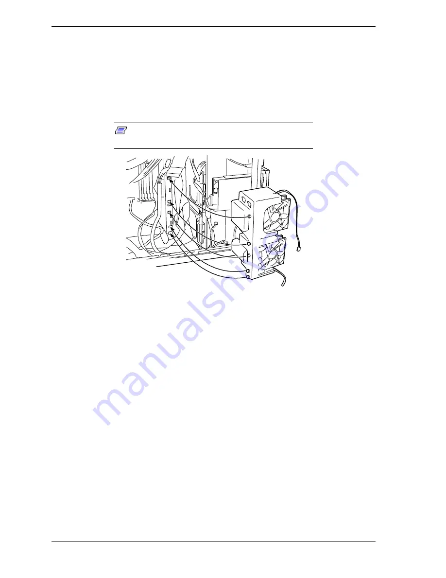
Insert the fan module and push it in until its tabs are fully seated in their
corresponding holes in the chassis (see Figure 4-8). Make sure the fan
module is oriented for the direction of airflow and that the fan cables coming
from the fan module are not restricted in any way. The fan cable must be
routed through the slot in the fan module.
4.
Reinstall the fan cover on the fan module. See
Installing the Fan Cover
earlier in this chapter.
Note:
Ensure that the cover is installed properly and
securely.
Figure 4-8. Installing the Fan Module
6.
Reinstall the left-hand side access panel on the system chassis. See
Installing
the Side Access Panel
earlier in this chapter.
7.
Plug in the system power cord(s) and power up the system.
Содержание EXPRESS5800/120Lf
Страница 1: ... U s e r s G u i d e EXPRESS5800 120Lf ...
Страница 2: ...NEC ...
Страница 3: ... U s e r s G u i d e EXPRESS5800 120Lf ...
Страница 9: ...Contents vii ...
Страница 10: ...viii Contents ...
Страница 36: ...1 20 System Overview ...
Страница 99: ...Upgrading Your System 4 13 Figure 4 9 Replacing the Real Time Clock Battery ...
Страница 146: ...4 60 Upgrading Your System Figure 4 60 Installing a Power Supply ...
Страница 170: ...5 24 Problem Solving ...
Страница 171: ...A Technical Specifications Server Unit ...
Страница 174: ...A 4 Technical Specifications ...
Страница 175: ...B Connectors Overview External Device Connector Pin Information ...
Страница 190: ...10 Glossary ...
Страница 196: ...Index 4 ...
Страница 197: ...xx ...
Страница 198: ... 456 01575 N00 ...


