


4-50
Upgrading Your System
!
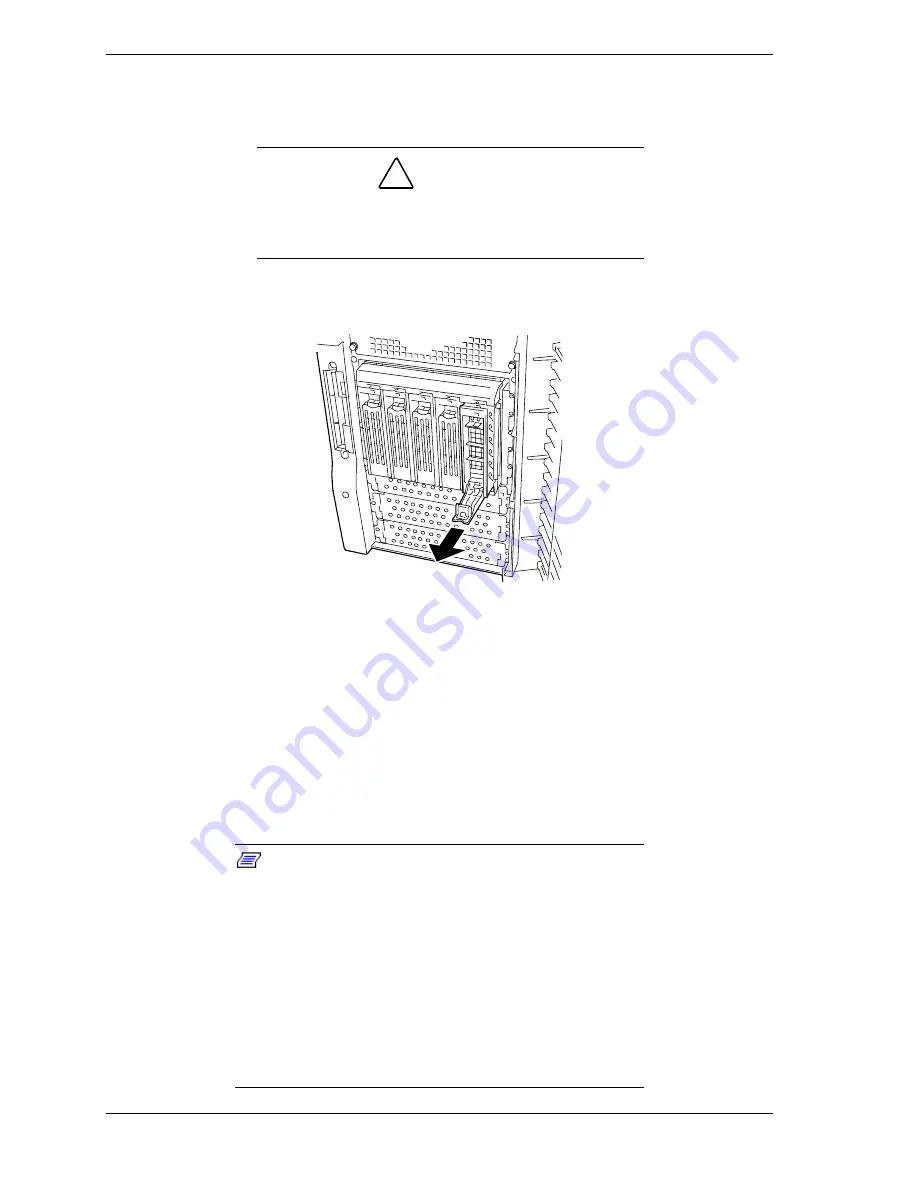
Grasp the disk carrier handle and pull the faulty disk drive out of the
bay far enough to disengage the drive connector from the backplane.
Wait 30 seconds until the drive spins down. See Figure 4-48.
!
CAUTION
D
rive manufacturer's caution against moving a disk drive
that is still spinning because of possible damage to the
drive.
!
Remove the carrier from of the drive bay.
Figure 4-48. Removing the Disk Carrier Tray
4.
Install the replacement drive carrier with drive into the bay, as follows:
!
Open the disk carrier handle lock.
!
While holding the drive carrier align it so that it engages the guide
rails in the drive bay. See Figure 4-46.
!
Push the carrier handle up until the handle clicks and locks in place.
5.
Close the front door on the system. If necessary, configure the system as
described in Chapter 3 "Configuring Your System".
Note:
In the disk array configuration, the auto rebuild
function can be used. The auto rebuild function can record
the information saved in a defected hard disk drive into the
new replaced disk drive in order to recover the server to the
state before the fault occurrence.
The auto build function is valid for disk arrays set to RAID1,
RAID5, or RAID0+1.
The auto rebuild is automatically started by hot-swapping a
defected hard disk drive. During the auto rebuild, the hard
disk drive individual SCSI drive activity/fault LED is lit green
or flashing amber.
Содержание EXPRESS5800/120Lf
Страница 1: ... U s e r s G u i d e EXPRESS5800 120Lf ...
Страница 2: ...NEC ...
Страница 3: ... U s e r s G u i d e EXPRESS5800 120Lf ...
Страница 9: ...Contents vii ...
Страница 10: ...viii Contents ...
Страница 36: ...1 20 System Overview ...
Страница 99: ...Upgrading Your System 4 13 Figure 4 9 Replacing the Real Time Clock Battery ...
Страница 146: ...4 60 Upgrading Your System Figure 4 60 Installing a Power Supply ...
Страница 170: ...5 24 Problem Solving ...
Страница 171: ...A Technical Specifications Server Unit ...
Страница 174: ...A 4 Technical Specifications ...
Страница 175: ...B Connectors Overview External Device Connector Pin Information ...
Страница 190: ...10 Glossary ...
Страница 196: ...Index 4 ...
Страница 197: ...xx ...
Страница 198: ... 456 01575 N00 ...


