Upgrading Your System 4-27
14.
Align the rounded notch in the retaining bracket with the threaded hole in
the expansion slot frame. The retaining bracket fits into the space that was
occupied by the expansion slot cover.
15.
Reinstall the setscrew in the threaded hole. Be sure to push the bracket slot
up against the setscrew before you tighten it. If this is not done, the bracket
may interfere with an adjacent bracket.
16.
Connect any external cables (if they are needed) to the installed option
board.
17.
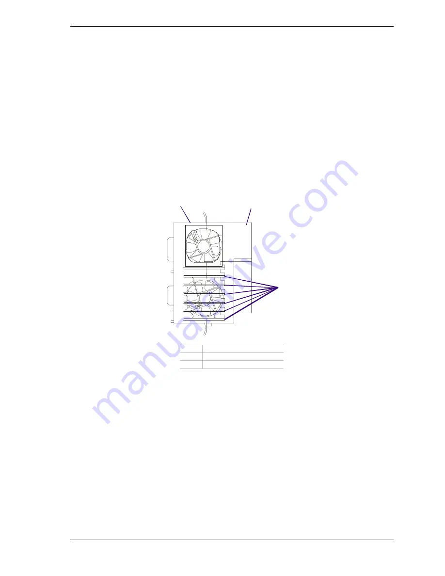
If you installed a full-length PCI board you must also align the rear edge of
the PCI board with the guide slots located in the fan cover (see Figure 4-26)
removed in step 4 above. Then reinstall the fan cover, see
Installing the Fan
Cover
earlier in this chapter.
A
B
C
A
Fan module
B
Fan cover
C
PCI board guide slots
Figure 4-26. Installing a Full-Length Option Board
18.
If applicable, reinstall all components removed earlier in step 5 and step 6.
19.
Replace the left side access panel and close the front door.
20.
Plug in the system power cord, and power on the system.
Содержание EXPRESS5800/120Lf
Страница 1: ... U s e r s G u i d e EXPRESS5800 120Lf ...
Страница 2: ...NEC ...
Страница 3: ... U s e r s G u i d e EXPRESS5800 120Lf ...
Страница 9: ...Contents vii ...
Страница 10: ...viii Contents ...
Страница 36: ...1 20 System Overview ...
Страница 99: ...Upgrading Your System 4 13 Figure 4 9 Replacing the Real Time Clock Battery ...
Страница 146: ...4 60 Upgrading Your System Figure 4 60 Installing a Power Supply ...
Страница 170: ...5 24 Problem Solving ...
Страница 171: ...A Technical Specifications Server Unit ...
Страница 174: ...A 4 Technical Specifications ...
Страница 175: ...B Connectors Overview External Device Connector Pin Information ...
Страница 190: ...10 Glossary ...
Страница 196: ...Index 4 ...
Страница 197: ...xx ...
Страница 198: ... 456 01575 N00 ...


