


Installation Guide
|
Comfort Pack T Series
with up to
95% Gas Heat
28
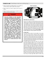
Burner Orifice
Burner orifice only needs to be replaced when a change in gas is
made. When ordering a replacement orifice, give BTU/H content
and specific gravity of gas, as well as the model and serial number
of the unit. Remove the gas manifold to remove the orifices.
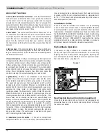
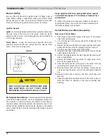
Ignition System
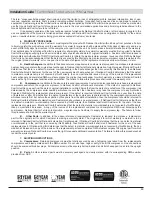
Igniter
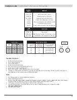
- Locate the igniter beneath the burner assembly. Disconnect
the wire; remove the screw and the igniter. Clean the igniter
assembly with an emery cloth. Spark gap must be maintained to
1/8" See Figure 6 below.
Flame Sensor
- Locate the flame sensor beneath the burner
assembly. Disconnect the wire; remove the screw and the flame
sensor. Clean with an emery cloth.
Figure 6
DUE TO HIGH VOLTAGE ON THE SPARK WIRE
AND ELECTRODE, DO NOT TOUCH WHEN
ENERGIZED. SEE HAZARD LEVELS, PAGE 5.
!
CAUTION
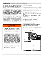
DSI Integrated Control Module
- The module monitors the operation
of the heater including ignition. The only replaceable component is
the 3 amp fuse. If the fuse is blown, the problem is most likely an
external overload. Correct the problem and replace the fuse. Do not
attempt to disassemble the control module. However, each heating
season check the lead wires for insulation deterioration and good
connections.
Proper operation of the direct spark ignition system requires
a minimum flame signal of 1.0 microamps as measured by a
microammeter.
For further information and check out procedure on the direct
spark ignition system, refer to the circuit board manufacturer’s
instructions supplied with the heater.
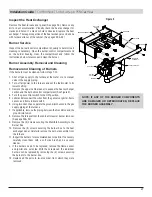
Venter Motor and Wheel Assembly
Removal of Venter Motor
1. Shut off gas supply to the furnace at the meter or at a manual
valve in the supply piping.
2. Turn off all power to the furnace and set the thermostat to its
lowest setting.
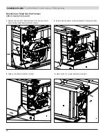
3. Remove the upper cabinet panel to expose the heat exchanger
section and the burner/control compartment (see Figure 2).
4. Turn the gas control switch to the OFF position.
5. Using two wrenches, separate the ground-joint union in the gas
supply piping at the furnace.
6. Remove the piping between the Gas Valve and the ground-joint
union. (If applicable).
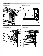
7. Remove the furnace from the cabinet for easier venter motor
removal. (See pages 30 & 32).
8. Label and disconnect the wires going to the venter motor as
well as the green ground wire on the venter motor.
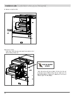
9. With the furnace removed from the cabinet, remove the (4)
screws securing the venter motor to the condensate collection
box.
10. Replace all the parts in reverse order from which they were
removed.
11. Follow the lighting instructions found on the furnace door to
return the furnace to operation. Verify proper operation after
servicing.
Содержание Comfort Pack CP9 T Series
Страница 2: ...2...