NCP Comfort Pack CP9 T Series Скачать руководство пользователя страница 12

Installation Guide

 | 

Comfort Pack T Series 

with up to 

95% Gas Heat 

12

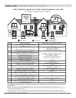
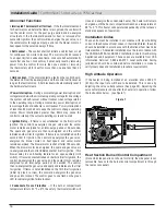
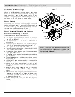
Vent Termination Clearances for Direct Vented Installations in the USA

For other gas venting information see page 21.

Operable

VENT  TERMINAL

AIR SUPPLY INLET

AREA WHERE TERMINAL

IS NOT PERMITTED

B

Fixed

Closed

c

B

N

F

B

P

D

E

J

B

B

B

L

A

Operable

Fixed

Closed

H

o

M

Inside Corner

Detail

G

A

Balcony -

with perpendicular side wall

Combustible &

Noncombustible

X = 24” (610 mm)

Z = 20” (508 mm)

I

K

x

L

Z

v

x

v

Item

Clearance Description

      US Installations (per ANSI Z223.1/NFPA 54)

A

Clearance above grade, veranda, porch, balcony or  

anticipated snow level

12 in. 


B


Clearance to a window or door that may be opened

9 in. for appliances > 10,000 Btu/h (3 kW) 

and ≤ 50,000 Btu/h (15 kW),


12 in. for appliances > 50,000 Btu/h (15 kW)

C

Clearance to a permanently closed window

For clearances not specified in ANSI Z223.1/NFPA 54,  

clearances shall be in accordance with  

local installation codes and  

the requirements of the gas supplier and the  

manufacturer’s installation instructions. 

See Note 1 

D

Vertical clearance to a ventilated soffit located above the termi-

nal within a horizontal distance of 2 feet from  

the center line of the terminal

E

Clearance to an unventilated soffit

F

Clearance to an outside corner

G

Clearance to an inside corner

H

Clearance to each side of the center line extended above elec-

trical meter or gas service regulator assembly

3 feet within 15 feet  

above the meter/regulator assembly.

I

Clearance to service regulator vent outlet

See Note 2

J

Clearance to non-mechanical air supply inlet to building or the 

combustion air inlet to any other appliance

9 in. for appliances > 10,000 Btu/h (3 kW) 

and ≤ 50,000 Btu/h (15 kW),


12 in. for appliances > 50,000 Btu/h (15 kW)

K

Clearance to a mechanical air supply inlet

3 feet

L

Clearance under a veranda, porch, deck, or balcony

See Notes 1 & 2

M

Clearance to each side of the center line extended above 

or below vent terminal of the furnace to a dryer or water heater 

vent, or other appliance’s vent intake or exhaust


12 in.

N

Furnace combustion air intake clearance to a water heater 

vent, dryer or other types of appliance exhausts

https://www.msn.com/en-us/feed 3 feet

O

Clearance from a plumbing vent stack

3 feet

P

Clearance above paved sidewalk or paved driveway 

located on public property

See Notes 1 & 2

Note: This table is based upon National codes for gas appliances, and are provided as a reference. Refer to Local codes which may supersede the standards and/

or recommendations.


Note 1:

 Avoid venting under a deck or large overhang. Recirculation could occur and cause performance or system problems. Ice build-up may occur. 

Note 2:

 For clearances note specified in ANSI Z223.1/NFPA 54, clearances shall be in accordance with local installation codes and the requirements of the gas supplier 

and the manufacturer’s installation instructions.
The vent for this appliance shall not terminate: 

a.

 Near the soffit vents or crawl space vents or other areas where condensate or vapor could create a nuisance or  

hazard or property damage; or  

b.

 Where condensate vapor could cause damage or could be detrimental to the operation of regulators, relief valves, or other equipment.

Specifications for venting subject to change without notice.

Содержание Comfort Pack CP9 T Series

Страница 1: ...PRODUCTS Go Thru the Wall CP9 T Series Please fill in the following information and file it for future reference MODEL NO ______________________________ SERIAL NO ______________________________ INSTA...

Страница 2: ...2...

Страница 3: ...Abnormal Functions page 18 High Altitude Operation page 18 20 Gas Piping Venting Pressures page 20 22 Ignition System page 22 23 Start up page 23 24 Special Notes for Extremely Cold Weather Areas page...

Страница 4: ...ck Nomenclature CP Product CP Comfort Pack 9 HeatType 8 80 Gas 9 95 Gas E Electric 4 Refrigerant 4 R410A 30 Clg Capacity 30 2 5Ton 43 Htg Capacity 43 43 MBH 50 50 MBH T Series T Tall A Option A Standa...

Страница 5: ...ATH WARNING WARNING DO NOT USE THIS APPLIANCE IF ANY PART HAS BEEN UNDER WATER IMMEDIATELY CALL A QUALIFIED SERVICE TECHNICIAN TO INSPECT THE APPLIANCE AND REPLACE ANY GAS CONTROL THAT HAS BEEN UNDER...

Страница 6: ...NJURY OR DEATH GAS FIRED APPLIANCES ARE NOT DESIGNED FOR USE IN HAZARDOUS ATMOSPHERES CONTAINING FLAMMABLE VAPORS OR COMBUSTIBLE DUST IN ATMOSPHERES CONTAINING CHLORINATED OR HALOGENATED HYDROCARBONS...

Страница 7: ...moval Carefully slide the chassis out of the cabinet by grasping the handles located beneath the evaporator coil drain pan and pulling toward you while keeping the chassis centered in the cabinet As t...

Страница 8: ...d through an exterior wall with the back end extending 3 4 past the outside wall surface Provide support inside the building for the unit near the return air opening There should be enough clearance a...

Страница 9: ...age whenever the slide out chassis has to be removed from the cabinet remove the secondary drain trap before sliding the chassis out After the chassis is reinstalled in the cabinet prime the trap with...

Страница 10: ...erless trap to free end of the vinyl tubing Use provided routing clamp and sheet metal screw to secure waterless trap to side panel Follow all applicable codes to route condensate from waterless trap...

Страница 11: ...of air to the unit a The front of the unit must be mounted tight to the inside of the architectural grille b A barrier must be provided to prevent recirculation of air to the unit mixing of inlet and...

Страница 12: ...learance to non mechanical air supply inlet to building or the combustion air inlet to any other appliance 9 in for appliances 10 000 Btu h 3 kW and 50 000 Btu h 15 kW 12 in for appliances 50 000 Btu...

Страница 13: ...an Electrical Code Part I C S A Standard C22 1 In addition the installer should be aware of any local ordinances or utility company requirements that might apply Check the rating plate for the supply...

Страница 14: ...ctrical safety precautions when exposed to live electrical components could result in death or serious injury WARNING The high voltage power supply must agree with the equipment nameplate OR Make cert...

Страница 15: ...h is located ce the top of the burner assembly It is factory set and i justable If the setpoint is reached the flame rollo interrupt the electric supply to the gas valve If the fla switch activates id...

Страница 16: ...m of 8 inches above finished floor See installation guide for vent termination clearances 38 13 16 26 57 64 7 57 64 43 17 13 16 7 21 32 28 3 31 32 2 1 64 RETURN LOW VOLTAGE THERMOSTAT CONNECTION JUCTI...

Страница 17: ...otor and waits for the pressure switch to close If the pressure switch does not close within 240 seconds of the venter motor energizing on 3 attempts the control green LED will flash two times and wil...

Страница 18: ...motor on heat speed and venter motor remains energized The blower motor is shut off after 180 seconds When the blower motor de energizes the spark and gas valve are re energized and the control initi...

Страница 19: ...ermanent marker fill in the pressure setting Adhere the label on the heater near the gas valve so that it is conspicuous to someone serving the valve NATURAL GAS HIGH HEATING VALUE MANIFOLD PRESSURE G...

Страница 20: ...apping for test gauge connection drip leg and ground union fitting If the supply air from the unit is ducted to space s outside the space containing the unit the return air must be ducted from outside...

Страница 21: ...w c and a maximum of 14 w c Normally field adjustment should not be required Before attempting to measure or adjust valve outlet gas pressure the inlet supply pressure must be within the specified ran...

Страница 22: ...L HAVING A TEMPERATURE RATING OF AT LEAST 105 C EXCEPT FOR LIMIT CONTROL FLAME ROLLOUT SWITCH AND SENSOR LEAD WIRES WHICH MUST BE 150 C PLEASE SEE HAZARD INTENSITY LEVELS CAUTION NOTE This is a fire t...

Страница 23: ...adequate for the load use turns the blower motor on heat speed and runs the venter motor The control will be in soft lockout and flashing fault code 3 before returning to normal operation When the sw...

Страница 24: ...ise to OFF Do not force 5 Close the access door Check Installation After Start Up If the heater is being derated for high altitude operation follow the instructions to adjust the valve outlet pressure...

Страница 25: ...d and replaced as needed and is not washable Substituting the air filter with media other than the type provided with the unit is not recommended since other materials may cause additional static pres...

Страница 26: ...OPERATE WITH MINIMUM MAINTENANCE TO ENSURE LONG LIFE AND SATISFACTORY PERFORMANCE A HEATER THAT IS OPERATED UNDER NORMAL CONDITIONS SHOULD BE INSPECTED AND CLEANED AT THE START OF EACH HEATING SEASON...

Страница 27: ...igure 2 4 Turn the gas control switch to the OFF position 5 Label and disconnect the wires from the gas valve igniter flame sensor and flame rollout switch 6 Using two wrenches separate the ground joi...

Страница 28: ...od connections Proper operation of the direct spark ignition system requires a minimum flame signal of 1 0 microamps as measured by a microammeter For further information and check out procedure on th...

Страница 29: ...red button on the switch 15 to 20 minutes are required for the switch to cool sufficiently for resetting A distinct click will be felt when the switch resets Operate the furnace If the flame rollout s...

Страница 30: ...he Furnace 1 Remove the wire from thermostat and from furnace control board to disconnect freeze protection heater After removing front panels 4 Remove the 2 screws indicated at the right 3 Slide out...

Страница 31: ...Installation Guide Comfort Pack T Series with up to 95 Gas Heat 31 5 Remove the patch plate 6 Remove the 11 screws 7 Remove front furnace baffle 8 Remove 2 screws...

Страница 32: ...connect wire harnesses and loosen hose clamp on flue before sliding furnace out Note Be careful with the secondary HX since the fins can be damaged easily When setting it down make sure it is tilted t...

Страница 33: ...MOP RLA LRA HP RLA LRA HP RLA CP943043TB 208 230 1 60 14 1 67 9 1 4 2 4 1 2 3 8 20 3 23 8 35 CP943050TB 208 230 1 60 14 1 67 9 1 4 2 4 1 2 3 8 20 3 23 8 35 Electrical Data Model Description CPWS Wall...

Страница 34: ...95 Gas Heat 34 Check Your Temperature Rise The temperature rise should be as follows 43MBH 50 F Nominal 35 F to 65 F 50MBH 55 F Nominal 40 F to 70 F In order to calculate CFM use the formula CFM BTU O...

Страница 35: ...tory Heat Speed Setting Comfort Pack Gas CFM and Temperature Rise 50 000 BTU Input UNIT SIZE COLOR SPEED 1 w c TD 2 w c TD 3 w c TD 4 w c TD 5 w c TD CP943050TB Red 1 1000 43 1 975 44 2 950 45 3 930 4...

Страница 36: ...SET POINT IS 230V FIELD ADJUSTMENT REQUIRED FOR 208V APPLICATION 1 2 3 4 5 SPEED TERMINAL 1 HIGH 2 MED HIGH 3 MED 4 MED LOW 5 LOW TB ORANGE BLUE BLUE RED BLACK BLUE YELLOW RED BLACK BLACK WHITE WHITE...

Страница 37: ...ed option thermostat 2 Dotted wiring installed by others 3 Caution if any of the original wiring as supplied with the appliance must be replaced it must be replaced with wiring material having a tempe...

Страница 38: ...ing control at the thermostat or 5 main power Replace combustion air proving switch 6 7 a If 24 volt is measured at the valve connections and valve remains closes replace valve b Check and tighten all...

Страница 39: ...r Grille Top 14256535 Combustion Air Baffle 14256536 Combustion Air Inlet 14256537 Unit Skid Strap 14256646 Furnace Channel 14256663 Furnace Parts Part Description Part Number 43 MBH 50 MBH Gas Furnan...

Страница 40: ...r Coil Mount 14256483 Drier 14275947 Outdoor Fan 14214042 Outdoor Motor Mount 14270101 Indoor Blower Motor 14270067 Blower Wheel 14214045 Blower Housing 14214044 Indoor Motor Mount 14270109 Air Divide...

Страница 41: ...g OHM Reading between Terminals C R __________ 5 Compressor Winding OHM Reading between Terminals R S __________ 6 Compressor Winding OHM Reading between Terminals C Ground __________ 7 Compressor Win...

Страница 42: ...espect to the goods and are in lieu of and exclude all other warranties express or implied arising by operation of law or otherwise including without limitation merchantability and fitness for a parti...

Страница 43: ...his procedure shall render the warranty void B Compressors In addition to the above referenced requirements Customer is also required to purchase a replacement compressor and return the original compr...

Страница 44: ...IM CP9 T Series with up to 95 Gas Heat 2024 HEATING A C EQUIPMENT NATIONAL COMFORT PRODUCTS National Comfort Products A Division of National Refrigeration Air Conditioning Products Inc 539 Dunksferry...

Отзывы: