Installation Guide
|
Comfort Pack T Series
with up to
95% Gas Heat
9
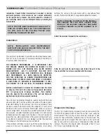
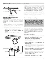
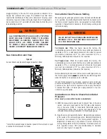
SECONDARY DRAIN TRAP
MUST BE INSTALLED
Drain Pan
3/4” I.D. Flexible Tubing Included
2”
min.
Pitch Downward 1” per 10ft.
Shaded Area Represents Components
Provided and Installed By Others
Highest Point Must Not Be Above
Bottom of Drain Pan
3/4” O.D. Drain Connection
(Primary Drain)
Secondary Evaporator Drain Trap
Install Instructions:
1.
The trap and 2
"
piece of clear flexible 1/2
"
ID tubing are
shipped loose to prevent damage. They should be installed after
the Comfort Pack unit is installed and the return air connection
completed.
2.
The trap must be primed (filled with water) for proper operation
of the secondary drain system. This may be done prior to
installation of the trap or after.
3.
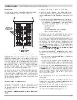
Insert trap into the grommet located in chassis base pan.
a. Apply force to section 1 (refer to drawing below)
b. Ensure at least .5" - 0.75" of tubing is inserted into the
grommet
c. PVC should be flush with drain pan connection
Secondary Drain Connection
Drain Pan
Apply
Force
1/2” I.D. Tubing
Grommet
Trap
Chassis Base
1
4.
Position the trap as shown and slide the 2
"
piece of clear flexible
tubing about 1
"
onto the top end of the trap. Slide the top of the
flexible tube on the trap onto the bottom of the 1/2
"
OD secondary
drain connection and push the top of the trap up. The trap should
be positioned so that there is only a small gap between the top of
the trap and the bottom of the secondary drain connection.
5.
To avoid damage whenever the slide-out chassis has to be
removed from the cabinet, remove the secondary drain trap before
sliding the chassis out. After the chassis is reinstalled in the
cabinet, prime the trap with water before reinstalling it.
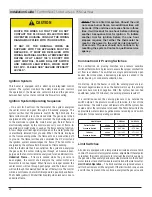
NOTE: THE HIGH EFFICIENCY FURNACES
PRODUCE CONDENSATE DURING OPERATION.
IN UNCONDITIONED SPACES, THE CONDENSATE
MAY BE SUSCEPTIBLE TO FREEZING. ENSURE
THE CONDENSATE IS ABLE TO DRAIN FREELY
AND PROPER CARE IS TAKEN TO PREVENT
DRAIN LINE FREEZING.
Furnace Condensate Drainage
A Condensate Drain Kit is provided with the unit. It contains a
waterless trap, two routing clamps, barbed hose elbow, barbed
hose coupling, two sheet metal screws, and two pieces of 5/8"
vinyl tubing. The unit has two options for the location of the
waterless trap.
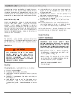
Instructions for Primary Location:
• Remove top right access panel to reveal burner compartment.
• Replace plastic insert located on side panel with rubber
grommet provided within the condensate drain kit.
• Locate the free end of the provided hose along the bottom of
the burner compartment.
• Connect the supplied barbed hose elbow to the hose from the
burner compartment.
• Cut approximately 1" off the long side of the vinyl tubing elbow.
(Verify length of the tubing needed to properly locate waterless
trap before cutting)
• Insert the short side of the vinyl tubing elbow into the grommet
on the side panel and connect to the barbed hose elbow.
• Install one of the supplied routing clamps over the connection
between the vinyl and barbed elbows and secure to the air
divider with a sheet metal screw (Note: there is a bite hole in
the divider under the insulation)
• Connect waterless trap to free end of vinyl tubing elbow.
Содержание Comfort Pack CP9 T Series
Страница 2: ...2...


