Installation Guide
|
Comfort Pack T Series
with up to
95% Gas Heat
22
Ignition System
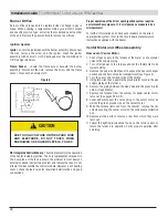
This heater is equipped with a direct spark integrated control
system. The system monitors the safety devices and controls
the operation of the blower and venter motors and the gas valve
between heat cycles. It also controls the blower for cooling.
Ignition System Operating Sequence
– On a call for heat from the thermostat, the system energizes
the venter motor and goes through a 30-second prepurge. The
system verifies that the pressure switch, the high limit and the
flame rollout switch are in the closed state. The gas valve is then
energized and the ignition system provides the high voltage spark
to the electrode to ignite the main burner gas. Burner flame is
electronically sensed by the control upon carry over of flame. (A
separate solid metal probe is used as the flame sensing function.
A low voltage electrical signal is imposed on the metal probe that
is electrically isolated from ground. When the flame impinges
on the flame sensing probe, the flame acts as a conduction path
to ground. The flame rectifies and completes the DC circuit and
the ignition system acknowledges the flame.) The fan motor is
energized by the system after 20 seconds of flame sensing.
After the thermostat has been satisfied, the system de-energizes
the gas valve, the venter motor goes through a 30-second post-
purge and the fan motor remains energized for an additional time.
Undesired Flame
– If flame is sensed while the gas valve is
de-energized, the control shall energize the venter motor and
blower motor on heat speed. When flame is no longer sensed, the
venter motor will run through post-purge, and the blower motor
will run through the selected heat blower off delay time. The control
will do a soft lockout, but will still respond to open limit and flame.
The FLAME (yellow) LED shall flash rapidly when lockout is due to
undesired flame.
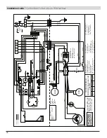
ROUTE THE WIRES SO THAT THEY DO NOT
CONTACT THE FLUE GAS COLLECTION BOX
OR VENTER HOUSING. CONSULT THE WIRING
DIAGRAM SUPPLIED WITH YOUR HEATER.
IF ANY OF THE ORIGINAL WIRES AS
SUPPLIED WITH THE APPLIANCE MUST BE
REPLACED, IT MUST BE REPLACED WITH
WIRING MATERIAL HAVING A TEMPERATURE
RATING OF AT LEAST 105°C, EXCEPT FOR
LIMIT CONTROL, FLAME ROLLOUT SWITCH
AND SENSOR LEAD WIRES, WHICH MUST
BE 150°C. PLEASE SEE “HAZARD INTENSITY
LEVELS”.
!
CAUTION
NOTE:
This is a fire trial system. Should the unit
not sense burner flame, two additional tries will
be made. If the unit does not sense flame in three
tries, it will lockout for one hour before initiating
another 3-sequence trial for ignition. To initiate
another trial for ignition before the one hour
elapses requires that either the thermostat be
reset or the power to the unit be interrupted for
30 seconds. The user should not continue to try
resetting the system. Contact a qualified service
agency.
Combustion Air Proving Switches
The combustion air proving switches are pressure sensitive
switches that monitor air pressure to ensure that proper combustion
air flow is available. The switches are single pole/normally open
devices that close when a decreasing pressure is sensed in the
venter housing, or condensate collection box.
On start-up when the heater is cold, the sensing pressure is at
the most negative level, and as the heater warms up, the sensing
pressure becomes less negative. After the system has reached
equilibrium (about 10 minutes), the sensing pressure levels off.
If a restriction causes the sensing pressure to be outside the
switch setpoint, the pressure switch will function to shut off the
main burner. The main burner will remain off until the system has
cooled and/or the resistance is reduced. The Table below lists the
approximate water column negative pressure readings and switch
setpoints for sea level operating conditions.
Heat Module
CHS0043
CHS0050
Collector Box
Pressure Switch
OPENS
-0.3+/-0.05
-0.6+/-0.05
CLOSES
-0.45 Max
-0.75 Max
Inducer
Pressure Switch
OPENS
-0.9+/-0.05
-0.7+/-0.05
CLOSES
-1.05 Max
-0.85 Max
Limit Switches
All units are equipped with a temperature activated auto reset limit
control. The control is factory set and is non-adjustable. If the setpoint
is reached, the limit control acts to interrupt the electric supply to
the gas valve. These safety devices provide protection in the case of
motor failure or lack of airflow due to a restriction at the inlet or outlet.
Limit Switch Operation
– The limit switches are ignored unless a
call for heat is present (W energized). If the limit switch is open and
a call for heat is present, the control de-energizes the gas valve and
Содержание Comfort Pack CP9 T Series
Страница 2: ...2...

