Chapter 4 Preparations for Installation
8
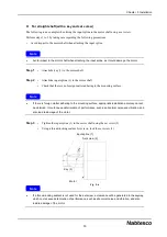
Be sure that no load is applied to the center pipe when attaching the protective cover. The oil seals
for the output shaft may be deformed, which could eventually cause leakage of the lubricant.
If the reduction gear is operated without the protective cover under the above conditions, lubricant
may leak from the oil seal on the output shaft.
If the required installation environment cannot be established/met, contact us in advance.
When using this product under special conditions (clean room, equipment for food, medical
equipment, concentrated alkali, high-pressure steam, etc.), contact our service representative in
advance.
Preparation of required components
4.2.
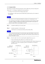
• The following components and materials are required for installing this product. Check the
components/materials and prepare them at each customer’s site.
• If the shape of the actual section differs from the illustration below, refer to the separately provided
“Outer dimensions” drawings and specification sheet.
• Prepare the components on the fixed side and the rotation side, which have been designed and
manufactured either based on the catalog or based on separately provided “Outer dimensions”
drawings and a specification sheet.
The actual components may differ from the required components shown in the above illustration,
depending on the customer’s equipment.
Important
Important
Fig. 4-1
Cap (accessory)
(RS-260A only)
Motor flange (accessory)
Hexagon socket head cap screw
(accessory)
Hexagon socket
head cap screw
Serrated lock
washer
Component on
rotation side
O-ring (accessory)
(RS-260A only)
Motor
Motor mounting bolt
Input spline (accessory)
Positioning pin for component on
fixed side
Tapped hole for
injecting/draining grease
Hexagon socket head
cap screw
Serrated lock
washer
Component on
fixed side


