Chapter 4 Preparations for Installation
9
Installation components
4.2.1.
The customer is required to prepare the following components used for incorporating the reduction gear
into the customer’s equipment.
(Component on fixed side)
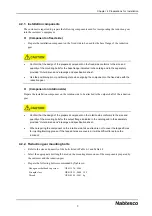
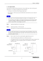
• Prepare the installation component on the fixed side to be used for the base flange of the reduction
gear.
Confirm that the design of the prepared component on the fixed side conforms to the size and
quantity of the mounting bolts for the base flange indicated in the catalog and in the separately
provided “Outer dimensions” drawings and specification sheet.
Use the positioning pin or positioning plate when aligning the component on the fixed side with the
reduction gear.
(Component on rotation side)
Prepare the installation component on the rotation side to be attached to the output shaft of the reduction
gear.
Confirm that the design of the prepared component on the rotation side conforms to the size and
quantity of the mounting bolts for the output flange indicated in the catalog and in the separately
provided “Outer dimensions” drawings and specification sheet.
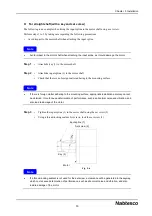
When preparing the component on the rotation side, take extra care not to cover the tapped holes
for injecting/draining grease. If the tapped holes are covered, it will be difficult to replace the
lubricant.
Reduction gear mounting bolts
4.2.2.
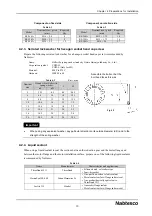
• Refer to the size and quantity of the bolts listed in Table 4-1 and Table 4-2.
• Select the appropriate bolt length based on the mounting dimensions of the components prepared by
the customer and the reduction gear.
• Prepare the following bolts recommended by Nabtesco:
Hexagon socket head cap screw
JIS B 1176 : 2006
Strength class
JIS B 1051 : 2000 12.9
Thread
JIS B 0209 : 2001 6g


