Chapter 5 Installation
23
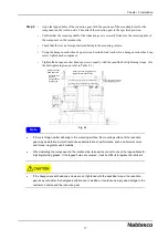
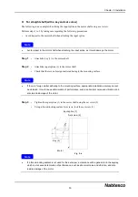
Step 5
• Check for deviation during rotation at
position A of the input spline (1). If the
deviation is within 50 µm, the procedure
is completed.
Step 6
• If the deviation of the input spline (1)
exceeds 50 µm, loosen the hexagon
socket head cap screws (4) and then
perform adjustment by repeating step 2
and subsequent steps.
Installing the motor
5.3.3.
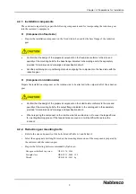
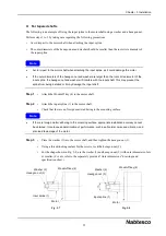
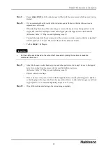
Perform steps 1 to 3 by taking care regarding the following precautions.
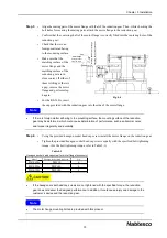
Step 1
• Check that the lubricant (PYRONOC UNIVERSAL N-6B) is coated onto the inside of the spline
on the input unit. (Do not wipe off the lubricant.)
• For the RS-260A, assemble the O-ring provided with the main unit into the input spline.
Use the O-ring that is provided with the reduction gear main unit.
Step 2
• Install the input spline on to the motor, and then directly insert the motor into the reduction gear.
At this point, make sure that the motor flange and the motor surface are in close contact without
any tilt.
• Do not forcibly press down on the motor.
If the motor is forcibly pressed down, it could damage the input spline, and motor.
If the lubricant is not applied to the inside of the spline on the input unit, the spline may be worn or
damaged.
Note
Note
Hexagon socket
cap screw (4)
Wedge-type frictional coupling (3)
Plate (2)
Enlarged drawing
Input spline (1)
Width
across
flat
Motor shaft
Gap X
Fig. 5-9
Fig. 5-10
Input spline (1)
Motor
O-ring
(RS-260A only)
Spline on input unit
Motor mounting bolt
(Arranged by the customer)
C
e
n
te
ri
n
g
sh
a
ft
o
f
m
o
to
r
C
e
n
te
ri
n
g
h
ol
e
o
f
m
o
to
r
fla
n
g
e

