Chapter 5 Installation
16
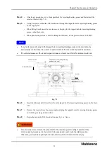
Step 1
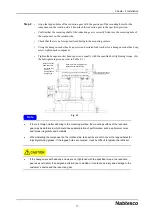
• Align the installation reference surface of the component on the fixed side with that of the
reduction gear. Then use a reamer to drill a positioning pin hole for the reduction gear and the
component on the fixed side. After that, tap the taper pin.
• Align the mounting holes of the reduction gear with the positions of the tapped holes for the
component on the fixed side. Then attach the reduction gear to the specified position.
• Check that there is no foreign matter adhering to the mounting surface.
• Using the hexagon socket head cap screw and serrated lock washer for a hexagon socket head cap
screw, tighten each component.
• Tighten the hexagon socket head cap screws equally with the specified bolt tightening torque. (For
the bolt tightening torque, refer to Table 5-1.)
If there is foreign matter adhering to the mounting surface, the mounting surface of the reduction
gear may be deformed, which could cause deterioration of performance, such as abnormal noise
and torque irregularity and durability.
When installing the component on the fixed side, take extra care not to cover the tapped holes for
injecting/draining grease. If the tapped holes are covered, it will be difficult to replace the lubricant.
If the hexagon socket head cap screws are not tightened with the specified torque, the reduction
gear does not deliver the designed performance. In addition, it could cause injury and damage to the
customer’s device and the reduction gear.
Note
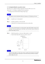
Fig. 5-2
Positioning pin for component
on fixed side
Hexagon socket
head cap screw
Serrated lock
washer
Installation reference surface of reduction gear
Component on fixed side
Tapped hole for
injecting/draining
grease
Installation reference surface of component on fixed side


