Chapter 5 Installation
15
Bolt tightening torque
5.2.
• Use the Nabtesco-recommended bolts for installing the reduction gear and tighten them with the
specified tightening torque.
(Reference: “4.2.2. Reduction gear mounting bolts”)
• Use the serrated lock washer for hexagon socket head cap screw to prevent the bolt from loosening
and protect the bolt seat surface from flaws.
(Reference: “4.2.3 Serrated lock washer for hexagon socket head cap screw”)
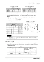
The following are the bolt tightening torques specified by Nabtesco. Be sure to check the following when
tightening the bolts.
Table 5-1
Nominal size × pitch
(mm)
Tightening torque*
(Nm)
Tightening force
(N)
M5 × 0.8
9.01 ± 0.49
9,310
M6 × 1.0
15.6 ± 0.78
13,180
M8 × 1.25
37.2 ± 1.86
23,960
M10 × 1.5
73.5 ± 3.43
38,080
M12 × 1.75
129 ± 6.37
55,100
M14 × 2.0
205±10.2
75,860
M16 × 2.0
319 ± 15.9
103,410
M20 × 2.5
493 ± 22.0
132,170
*
The tightening torque values listed are for steel or cast iron material.
If aluminum or stainless-steel is used for the bolt, limit the tightening torque. When tightening the
bolt with the limited torque, confirm that there is no strength problem by taking the transmission
torque and load moment into due consideration.
Installation work
5.3.
The installation procedure may differ from the contents of this manual, depending on the shape of
the components designed by the customer.
Installing the reduction gear
5.3.1.
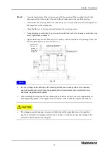
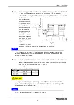
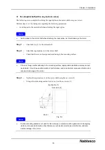
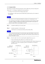
The following describes the installation of the reduction gear.
Perform steps 1 to 5 by taking care regarding the following precautions.
• The reduction gear is coated with rust prevention oil before shipping. Wipe off the rust prevention oil
as necessary during installation. In particular, do not fail to wipe off the rust prevention oil from the
mounting surface and the bolt seat surface.
• Use the installation reference surface of the reduction gear or a positioning pin when aligning the
component on the fixed side with the reduction gear.
Important
Important


