Page 54 MSI-3750CS RF Weighmeter • User Guide
3750CS
C
ELL
S
CALE RF DIGITAL WEIGHT INDICATOR
®
To Program the Local 3750CS Set Point Message
Set Point messages are entered as ASCII “Strings”. You can combine MSI “@ Codes” in embed weight, date, and time information in the Set Point string.
See the Comm Port section following for a table of “@ Codes”.
1
SPSTRING
1. 00
2
ºººººººº
3
-
4
(enters last Character)
4
SP STRING
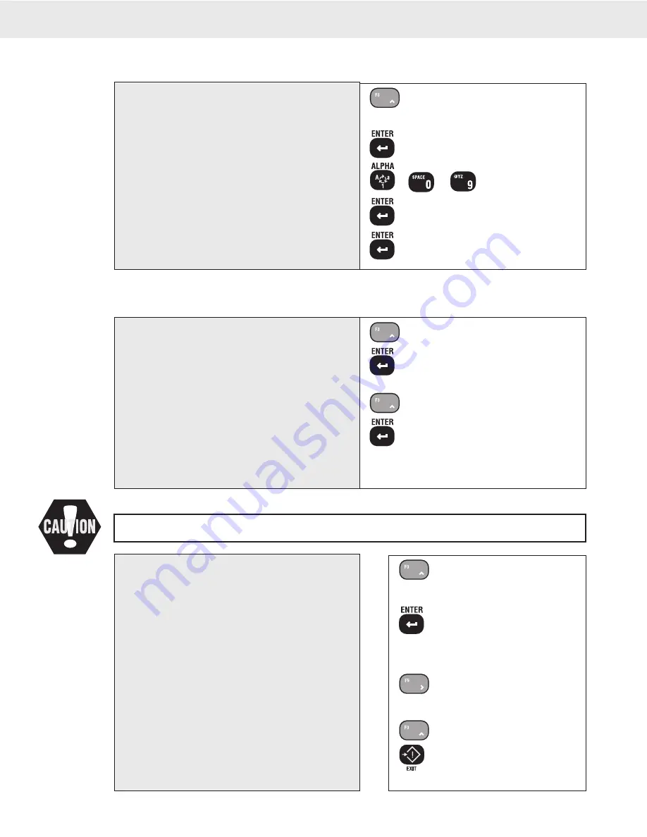
1) Use the UP key to scroll to “SPSTRING”.
2) Push ENTER. The current set point message string
is shown. The numeric digits indicate the character
position and ASCII value in decimal notation.
3) Use the Alpha key to change from numbers to letters.
Use the alpha-numeric keys to type in the message.
See page 90 for details on inputting alphanumeric
characters.
4) Push ENTER twice to store the string.
The Set Point Message String is complete. To add
functionality to the Set Point, continue on to any or
all of the following procedures or push the EXIT
(SETUP) key to return to normal scale operation.
1
SCREEN
2
NORMAL
3
BLINK
4
SCREEN
1) Use the UP key to scroll to “SCREEN”.
2) Push ENTER. The current screen mode is shown.
The numeric digits indicate the character position
and ASCII value in decimal notation.
3) Use the UP key to scroll through the Screen mode
choices: Blink, Blank, Message, and Normal.
In this example, we’ll choose “BLINK”.
4) Push ENTER to store the screen mode.
The LCD Mode has been set. To add functionality
to the Set Point, continue on to any or all of the
following procedures or push the EXIT (SETUP)
key to return to normal scale operation.
To Control the LCD Screen with a Set Point
A Set Point can cause the LCD Screen to Blink or to Blank out, or display the ASCII SP Message. In this example we’ll set up the LCD to blink when
the Set Point is true.
To Test the Set Points
1
TEST SP
OFF
2
SETPNT 1
On
3
SETPNT 1
4
SETPNT 2
4
TEST SP
1) Use the UP or DOWN key to scroll to “TEST SP”.
2) Push ENTER. Set Point 1 shows on the message
display. The numeric display indicates OFF or
ON.
3) Use the LEFT or RIGHT key to toggle between
“OFF” and “ON”. Observe the behaviour of relays
and messages.
LCD Screen behaviour is not testable, only relay closures , local Com Port
output, and CS outputs are effected.
4) Use the UP key to scroll through all the applicable
Set Points. Repeat step 3 to test Set Point Function.
5) Push EXIT (Setup) to return to the Set Points Setup
menus.
This following procedure will turn on and off any device connected to the relays. Make sure that doing
so will not cause a safety hazard or damage property or goods.


