background image

 Dashboard 4 - 9

4.1.1.2.7 Wireless Clients

Inventory

The 

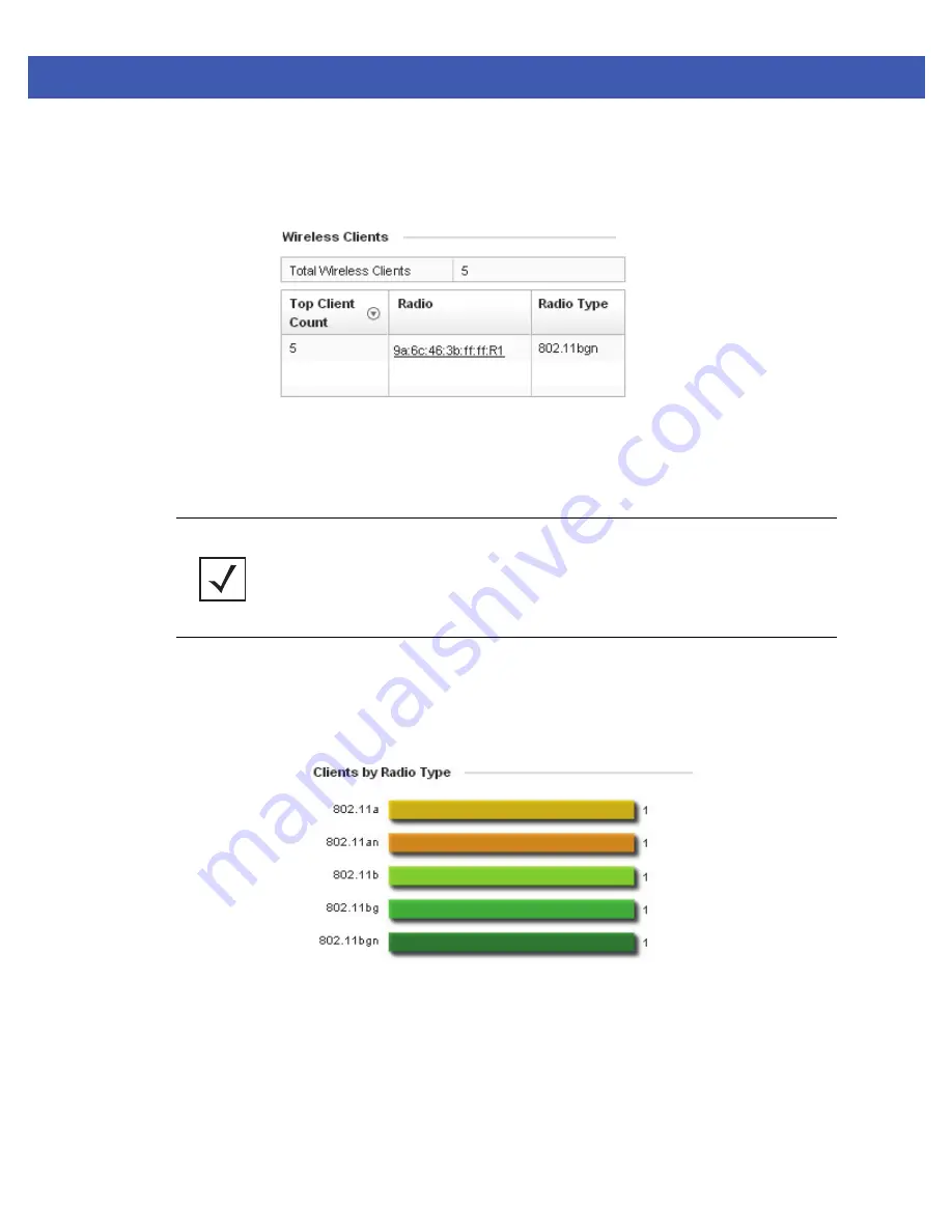
Wireless Clients

 field displays information about the wireless clients managed by the selected access point.

Figure 4-10

Wireless Clients field

Information within the 

Wireless Clients 

field is presented in two tables. The first table lists the total number of wireless 

clients managed by this access point. The second table lists an ordered ranking of radios based on their supported client 
count. Use this information to assess if an access point managed radio is optimally deployed in respect to its radio type 
and intended client support requirements.

4.1.1.2.8 Clients by Radio Type

Inventory

The 

Clients by Radio Type

 field displays a bar graph illustrating the number of connected clients currently operating on 

supported radio bands. 

Figure 4-11

Client On Channel field

For 5 GHz, clients are displayed supporting the 

802.11a

 and 

802.11an

 radio bands. For 2.4 GHz, clients are displayed 

supporting the 

802.11b

802.11bg

, and 

802.11bgn

 radio bands. Use this information to determine if all the access point’s 

client radio bands are optimally supported for the access point’s radio coverage area.

NOTE: 

 AP-7131, AP-6532 and AP-7161 model access points can support up to 256 client 

connections to a single access point. AP-6511 and AP-6521 model access points (both 
single radio models) can support up to 128 client connections per access point.

Содержание WiNG 5

Страница 1: ...Motorola Solutions WiNG 5 Access Point System Reference Guide ...

Страница 2: ......

Страница 3: ... 5 2 2 4 Status Icons 2 6 2 2 5 Configurable Objects 2 6 2 2 6 Configuration Objects 2 8 2 2 7 Configuration Operation Icons 2 9 2 2 8 Access Type Icons 2 9 2 2 9 Administrative Role Icons 2 10 2 2 10 Device Icons 2 11 Chapter 3 Quick Start 3 1 Using the Initial Setup Wizard 3 2 Chapter 4 Dashboard 4 1 Dashboard 4 2 4 1 1 Dashboard Conventions 4 2 4 1 1 1 Health 4 3 4 1 1 2 Inventory 4 7 4 2 Netwo...

Страница 4: ...5 89 5 3 5 13 Miscellaneous Network Configuration 5 91 5 3 5 14 Profile Network Configuration and Deployment Considerations 5 92 5 3 6 Profile Security Configuration 5 92 5 3 6 1 Defining Profile VPN Settings 5 93 5 3 6 2 Defining Profile Security Settings 5 112 5 3 6 3 Setting the Certificate Revocation List CRL Configuration 5 113 5 3 6 4 Setting the Profile s NAT Configuration 5 114 5 3 6 5 Set...

Страница 5: ...guration 5 240 5 10 2 9 Overriding a Forwarding Database Configuration 5 250 5 10 2 10 Overriding a Bridge VLAN Configuration 5 252 5 10 2 11 Overriding a Cisco Discovery Protocol Configuration 5 256 5 10 2 12 Overriding a Link Layer Discovery Protocol Configuration 5 257 5 10 2 13 Overriding a Miscellaneous Network Configuration 5 259 5 10 3 Overriding a Security Configuration 5 260 5 10 3 1 Over...

Страница 6: ...ion 7 1 Policy Based Routing PBR 7 2 7 2 L2TP V3 Configuration 7 8 7 3 Network Deployment Considerations 7 12 Chapter 8 Security Configuration 8 1 Wireless Firewall 8 2 8 1 1 Defining a Firewall Configuration 8 2 8 1 2 Configuring IP Firewall Rules 8 13 8 1 3 Configuring MAC Firewall Rules 8 16 8 2 Wireless IPS WIPS 8 20 8 3 Device Categorization 8 29 8 4 Security Deployment Considerations 8 31 Ch...

Страница 7: ...Managing File Transfers 12 7 12 1 3 Using the File Browser 12 9 12 1 4 AP Upgrades 12 10 12 1 5 Controller Re election 12 14 12 2 Certificates 12 16 12 2 1 Certificate Management 12 16 12 2 2 RSA Key Management 12 26 12 2 3 Certificate Creation 12 31 12 2 4 Generating a Certificate Signing Request CSR 12 34 12 3 Smart RF 12 37 12 3 1 Managing Smart RF for a RF Domain 12 37 12 4 Operations Deployme...

Страница 8: ...Routing 13 56 13 3 9 Radios 13 57 13 3 9 1 Status 13 59 13 3 9 2 RF Statistics 13 61 13 3 9 3 Traffic Statistics 13 63 13 3 10 Mesh 13 64 13 3 11 Interfaces 13 66 13 3 11 1 General Statistics 13 67 13 3 11 2 Viewing Interface Statistics Graph 13 72 13 3 12 PPPoE 13 72 13 3 13 OSPF 13 74 13 3 13 1 OSPF Summary 13 75 13 3 13 2 OSPF Neighbors 13 78 13 3 13 3 OSPF Area Details 13 81 13 3 13 4 OSPF Rou...

Страница 9: ...13 122 13 3 21 Certificates 13 124 13 3 21 1 Trustpoints 13 125 13 3 21 2 RSA Keys 13 128 13 3 22 WIPS 13 129 13 3 22 1 WIPS Client Blacklist 13 130 13 3 22 2 WIPS Events 13 131 13 3 23 Sensor Servers 13 132 13 3 24 Captive Portal 13 133 13 3 25 Network Time 13 135 13 3 25 1 NTP Status 13 136 13 3 25 2 NTP Association 13 138 13 3 26 Load Balancing 13 139 13 4 Wireless Client Statistics 13 141 13 4...

Страница 10: ...viii WiNG 5 Access Point System Reference Guide ...

Страница 11: ...el purchased Motorola Solutions WING 5 Access Point System Reference Guide this guide Describes the configuration of either a Standalone AP or Virtual Controller AP using the access point s initial setup wizard and resident WING 5 access point specific software Motorola Solutions WING 5 Controller System Reference Guide Describes the configuration of a Dependent mode AP using the WING 5 controller...

Страница 12: ...items Button names on a screen Bullets indicate Action items Lists of alternatives Lists of required steps that are not necessarily sequential Sequential lists e g those that describe step by step procedures appear as numbered lists CAUTION Indicates conditions that can cause equipment damage or data loss WARNING Indicates a condition or procedure that could result in personal injury or equipment ...

Страница 13: ...ndependent and dependent architectures to create a smart network that meets the connectivity quality and security needs of each user and their applications based on the availability of network resources including wired networks By distributing intelligence and control amongst access points a WiNG 5 network can route directly via the best path as determined by factors including the user location th...

Страница 14: ...igned specifically for AP 7131 AP 6532 AP 7161 AP 6511 and AP 6521 model access It does not describe the version of the WING 5 software designed for use with the RFS4000 RFS6000 RFS7000 and NX9000 For information on using WING 5 in a controller managed network go to http supportcentral motorola com support product manuals do ...

Страница 15: ...ire an unnecessary backhaul Within a WiNG 5 network up to 80 of the network traffic can remain on the wireless mesh and never touch the wired network so the 802 11n load impact on the wired network is negligible In addition latency and associated costs are reduced while reliability and scalability are increased A WiNG 5 network enables the creation of dynamic wireless traffic flows so bottlenecks ...

Страница 16: ...1 4 WiNG 5 Access Point System Reference Guide ...

Страница 17: ...4 other access points of the same model and share data amongst managed access points In Standalone mode an access point functions as an autonomous non adopted access point servicing wireless clients If adopted to controller an access point is reliant on its connected controller for its configuration and management For information on how to access and use the access point s Web UI see Accessing the...

Страница 18: ... 255 255 0 3 To derive the access point s IP address using its MAC address a Open the Windows calculator be selecting Start All Programs Accessories Calculator This menu path may vary slightly depending on your version of Windows b With the Calculator displayed select View Scientific Select the Hex radio button c Enter a hex byte of the access point s MAC address For example F0 d Select the Dec ra...

Страница 19: ... 7 Select the Login button to load the management interface If this is the first time the management interface has been accessed the first screen to display will prompt for a change of the default access point password Then a dialogue displays to start the initial setup wizard For more information on using the initial setup wizard see Using the Initial Setup Wizard on page 3 2 ...

Страница 20: ...lists global icons available throughout the interface Logoff Select this icon to log out of the system This icon is always available and is located at the top right hand corner of the UI Add Select this icon to add a row in a table When this icon is selected a new row is created in the table or a dialog box opens where you can enter values for that particular list Delete Select this icon to remove...

Страница 21: ...policy and select this button Entry Updated Indicates a value has been modified from its last saved configuration Entry Update States that an override has been applied to a device s profile configuration Mandatory Field Indicates the control s value is a mandatory configuration item You will not be allowed to proceed further without providing all mandatory values in this dialog Error in Entry Indi...

Страница 22: ...g Intervention might still be required to resolve subsequent warnings Success Indicates everything is well within the network or a process has completed successfully without error Information This icon always precedes information displayed to the user This may either be a message displaying progress for a particular process or may just be a message from the system Device Configuration Represents a...

Страница 23: ...des of the network RF Domain States an RF Domain configuration has been impacted RF Domain implement location based security restrictions applicable to all VLANs in a particular physical location Firewall Policy Indicates a Firewall policy has been impacted Firewalls provide a barrier that prevent unauthorized access to secure resources while allowing authorized access to external and internal res...

Страница 24: ...resses RADIUS Group Indicates the configuration of RADIUS Group is being defined and applied A RADIUS group is a collection of RADIUS users with the same set of permissions RADIUS User Pools States a RADIUS user pool is being applied RADIUS user pools are a set of IP addresses that can be assigned to an authenticated RADIUS user RADIUS Server Policy Indicates a RADIUS server policy is being applie...

Страница 25: ... this icon link to view the different logs generated by the user interface FLEX and the error logs Revert When selected any changes made after the last saved configuration are restored back to the last saved configuration Commit When selected all changes made to the configuration are written to the access point Once committed changes cannot be reverted Save When selected changes are saved to the a...

Страница 26: ...ed to configure some general settings like boot parameters licenses auto install image upgrades etc Network Indicates network user privileges A network user is allowed to configure all wired and wireless parameters like IP configuration VLANs L2 L3 security WLANs radios etc Security Indicates security user privileges A security level user is allowed to configure all security related parameters Mon...

Страница 27: ... indicates system wide impact Cluster This icon indicates a cluster A cluster is a set of access points that work collectively to provide redundancy and load sharing Access Point This icon indicates any access point that is a part of the network Wireless Client This icon defines any wireless client connected within the access point managed network ...

Страница 28: ...2 12 WiNG 5 Access Point System Reference Guide ...

Страница 29: ...amline the process of initially accessing the wireless network The wizard defines the access point s operational mode deployment location basic security network and WLAN settings For instructions on how to use the initial setup wizard see Using the Initial Setup Wizard on page 3 2 ...

Страница 30: ...ogin screen displays Figure 3 1 Web UI Login Screen 2 Enter the default username admin in the Username field 3 Enter the default password motorola in the Password field 4 Click the Login button to load the management interface NOTE When logging in for the first time you re prompted to change the password to enhance device security in subsequent logins NOTE If you get disconnected when running the ...

Страница 31: ...tup wizard and move directly to access point s main user interface UI by selecting Not Now The setup wizard can also be disabled until the next time the access point is rebooted by selecting Never NOTE The Initial Setup Wizard displays the same pages and content for each access point model supported The only difference being the number of radios configurable by model as an AP 7131 model can suppor...

Страница 32: ...Navigation Panel and Introduction for the configuration activities comprising the access point s initial setup A green checkmark to the left of an item in the Navigation Panel defines the listed task as having its minimum required configuration parameters set correctly A red X defines the task as still requiring at least one parameter be defined correctly ...

Страница 33: ...vious screen in the Navigation Panel without saving your updates 6 Select Next The Initial AP Setup Wizard displays the Access Point Type screen to define the access point s Standalone versus Virtual Controller AP functionality and the way the access point is adopted to a controller NOTE While you can navigate to any page in the navigation panel you cannot complete the Initial AP Setup Wizard unti...

Страница 34: ...e model Standalone AP Select this option to deploy this access point as an autonomous fat access point A standalone AP isn t managed by a Virtual Controller AP or adopted by a RFS series controller NOTE If designating the access point as a Standalone AP Motorola Solutions recommends the access point s UI be used exclusively to define its device configuration and not the CLI The CLI provides the ab...

Страница 35: ...l also need to define whether the access point receives an IP address using DHCP or if IP resources are provided statically Figure 3 6 Initial Setup Wizard Adoption Settings 8 Select Next The Initial AP Setup Wizard displays the Access Point Mode screen to define the access point s routing or bridging mode functionality NOTE The best way to administer a network populated by numerous access points ...

Страница 36: ...yment supported by just a single access point Bridge Mode In Bridge Mode the access point depends on an external router for routing LAN and WAN traffic Routing is generally used on one device whereas bridging is typically used in a larger density network Thus select Bridge Mode when deploying this access point with numerous peer APs supporting clients on both the 2 4 and 5GHz radio bands 10 Select...

Страница 37: ...able When selecting this option define the following DHCP Server and Domain Name Server DNS resources as those fields will become enabled on the bottom portion of the screen Use on board DHCP server to assign IP addresses to wireless clients Select the checkbox to enable the access point s DHCP server to provide IP and DNS information to clients on the LAN interface Range Enter a starting and endi...

Страница 38: ...or converting the name into its corresponding IP address cannot locate the matching IP address Primary DNS Enter an IP Address for the main Domain Name Server providing DNS services for the access point s LAN interface Secondary DNS Enter an IP Address for the backup Domain Name Server providing DNS services for the access point s LAN interface 12 Select Next The Initial AP Setup Wizard displays t...

Страница 39: ...xternal network This ports available differ depending on the access point model deployed Access point models with a single port have this option fixed Enable NAT on the WAN Interface Select the checkbox to allow traffic to pass between the access point s WAN and LAN interfaces 14 Select Next The Initial AP Setup Wizard displays the Radio Configuration screen to define radio support for the 2 4GHz ...

Страница 40: ...4GHz and another for 5GHz support if using a dual or three radio model when supporting clients in both the 802 11bg and 802 11n bands Power Level Use the spinner control to select a 1 23 dBm minimum power level to assign to this radio in selected 2 4 or 5 0 GHz band 1 dBm is the default setting Channel Mode Select either Random Best or Static Select Random for use with a 802 11a n radio To comply ...

Страница 41: ...int managed network If dedicating a radio as a sensor resource a primary and secondary ADSP server must be specified as an ADSP management resource Disable the Radio Select this option to disable this radio thus prohibiting it from either providing WLAN or sensor support Verify this course action with your network administrator before rendering the radio offline 16 Select Next The Initial AP Setup...

Страница 42: ...ers is 32 Do not use This is a required parameter for each WLAN WLAN Type Set the data protection scheme used by clients and access points within the WLAN The following options are available No Authentication and no Encryption Select this option to provide no security between the access point and connected clients on this WLAN Captive Portal Authentication and No Encryption Select this option to u...

Страница 43: ...type requires a RADIUS server to validate user credentials designate whether the access point is using an External RADIUS Server resource or the access point s own Onboard RADIUS Server If using an external RADIUS server resource provide the IP address of the external server and the shared secret used to authenticate the request 18 Select Next The Initial AP Setup Wizard displays the RADIUS Server...

Страница 44: ...rname If adding a new user account create a username up to X characters in length The username cannot be revised if modifying the user configuration This is a required parameter Password Provide or modify a password between X X characters in length entered each time a requesting client attempts access to the AP managed network using the access point s onboard RADIUS server This is a required param...

Страница 45: ...mation The system time can either be set manually or be supplied by a dedicated Network Time Protocol NTP resource Figure 3 13 Initial AP Setup Wizard Country Date Time 23 Refer to the Country and Time Zone field to set the following device deployment information Location Define the location of the access point The Location parameter acts as a reminder of where the AP can be located within the Mot...

Страница 46: ... used to provide system time to the access point Once the IP address is entered the Network Time Protocol NTP functionality is engaged automatically for synchronization with the NTP resource 26 If an NTP resource is unavailable set the System Date and Time calendar date time and AM PM designation 27 Optionally enter the IP address of a server used to provide system time to the access point Once th...

Страница 47: ...9 If the configuration displays as intended select the Save Commit button to implement these settings to the access point s configuration If additional changes are warranted based on the summary either select the target page from the Navigational Panel or use the Back button ...

Страница 48: ...3 20 WiNG 5 Access Point System Reference Guide ...

Страница 49: ...int managed network Use the dashboard to review the current network topology assess the network s component health and diagnose problematic device behavior By default the Dashboard screen displays the System Dashboard which is the top level in the device hierarchy The dashboard provides the following tools and diagnostics Dashboard Network View ...

Страница 50: ... the System menu item on the upper left hand side of the UI and select either an access point or connected client The Dashboard displays the Health tab by default Figure 4 1 Dashboard screen Health tab 4 1 1 Dashboard Conventions The Dashboard displays device information using the following conventions Health Displays information about the state of the access point managed network Inventory Displa...

Страница 51: ...ate of the access point managed network Figure 4 2 Dashboard screen Health tab Information in this tab is classified as Device Details Radio RF Quality Index Radio Utilization Index Client RF Quality Index 4 1 1 1 1 Device Details Health The Device Details field displays model and version information ...

Страница 52: ...ge of the overall effectiveness of the RF environment It s a function of the data rate in both directions the retry rate and the error rate Figure 4 4 Radio RF Quality Index RF Quality displays as the average quality index for the single RF Domain utilized by the access point The table lists the bottom five 5 RF quality values for the RF Domain The quality is measured as 0 20 Very poor quality 20 ...

Страница 53: ...m is used by the access point Traffic utilization is defined as the percentage of throughput relative to the maximum possible throughput Refer to the number or errors and dropped packets to assess radio performance relative to the number of packets both transmitted and received Periodically select Refresh at the bottom of the screen to update the radio utilization information displayed Figure 4 5 ...

Страница 54: ... 5 performing client radios connected to the access point The RF Quality Index measures the overall effectiveness of the RF environment as a percentage Its a function of the connect rate in both directions as well as the retry rate and the error rate The quality is measured as 0 20 Very poor quality 20 40 Poor quality 40 60 Average quality 60 100 Good quality Client MAC Displays the factory encode...

Страница 55: ...Inventory screen affords a system administrator an overview of the number and state of managed devices The screen contains links to display more granular data specific to a specific radio Figure 4 7 Dashboard screen Inventory tab The Inventory screen is partitioned into the following fields Radio Types WLAN Utilization Wireless Clients Clients by Radio Type ...

Страница 56: ...sh at the bottom of the screen to update the radio information 4 1 1 2 6 WLAN Utilization Inventory The WLAN Utilization field displays the top 5 WLANs utilized by this access point in respect to client support The utilization index measures how efficiently the RF medium is utilized It is defined as a percentage of the current throughput relative to the maximum throughput possible The quality is m...

Страница 57: ...requirements 4 1 1 2 8 Clients by Radio Type Inventory The Clients by Radio Type field displays a bar graph illustrating the number of connected clients currently operating on supported radio bands Figure 4 11 Client On Channel field For 5 GHz clients are displayed supporting the 802 11a and 802 11an radio bands For 2 4 GHz clients are displayed supporting the 802 11b 802 11bg and 802 11bgn radio ...

Страница 58: ...be utilized to review device performance and utilization as well as the RF band channel and vendor For more information see Network View Display Options on page 4 11 To review a device s Network Topology select Dashboard Network View Figure 4 12 Network View Topology The left hand side of the Network View display contains an expandable System Browser where access points can be selected and expande...

Страница 59: ...ork View Options 2 The following display filter options are available None Select this option to keep the Network View display as it currently appears without any additional color or device interaction adjustments Utilization Select this option to filter based on the percentage of current throughput relative to maximum throughput Utilization results include Red Bad Utilization Orange Poor Utilizat...

Страница 60: ...ded text field and select the Update button to isolate located variables in blue within the Network View display 3 Select the Update button to update the display with the changes made to the filter options Select Close to close the options field and remove it from the Network View 4 2 2 Device Specific Information Network View A device specific information screen is available for individual device...

Страница 61: ...wever access point configurations may need periodic refinement and overrides from their original RF Domain administered design For more information see RF Domain Overrides on page 5 181 Profiles enable administrators to assign a common set of configuration parameters and policies to access points of the same model Profiles can be used to assign shared network wireless and security parameters to ac...

Страница 62: ...t s RF Domain configuration may need periodic refinement from its original RF Domain designation Unlike a RFS series controller an access point supports just a single RF domain Thus administrators should be aware that overriding an access point s RF Domain configuration results in a separate configuration that must be managed in addition to the RF Domain configuration Thus a configuration should o...

Страница 63: ...created by or impacting the RF Domain Time Zone Set the geographic time zone for the RF Domain The RF Domain can contain unique country codes and time zone information to access points deployed across different states or countries thus making them ideal for managing device configurations across different geographical deployments Country Define the two digit country code set for the RF Domain The c...

Страница 64: ...onds for updates retrieved from the access point Window Index Use the spinner control to set a numerical index used as an identifier for each RF Domain statistics defined Sample Interval Use the spinner control to define the interval in seconds used by the access point to capture windowed statistics supporting the RF Domain configuration The default is 5 seconds Window Size Use the spinner control...

Страница 65: ... RF Domain WIPS is not supported on a WLAN basis rather sensor functionality is supported on the access point radio s available to each managed WLAN When an access point radio is functioning as a WIPS sensor it s able to scan in sensor mode across all legal channels within the 2 4 and 5 0 GHz band Sensor functionality is not provided by the access point alone The access point works in conjunction ...

Страница 66: ...Reference Guide 6 Use the spinner control to specify the Port of each WIPS server The default port is 443 7 Select OK to save the changes to the AirDefense WIPS configuration or select Reset to Revert to the last saved configuration ...

Страница 67: ...rations overwrite their profile assignments until the profile can be re applied to the access point Each access point model is automatically assigned a default profile The default profile is available within the access point s configuration file Default profiles are ideal for single site deployments where several access points may need to share a common configuration For more information refer to ...

Страница 68: ...on 5 Select OK to save the changes made to the general profile configuration Select Reset to revert to the last saved configuration AutoKey Select the radio button to enable an autokey configuration for the NTP resource The default setting is disabled Key If an autokey is not being used manually enter a 64 character maximum key the access point and NTP resource share to securely interoperate Prefe...

Страница 69: ... determines the maximum power provided by the POE device and the budget available to the access point The CPLD also determines the access point hardware SKU model and the number of radios If the access point s POE resource cannot provide sufficient power to run the access point with all intended interfaces enabled some of the following interfaces could be disabled or modified The access point s tr...

Страница 70: ...ode and the radio s 802 3at Power Mode Use the drop down menu to define a mode of either Range or Throughput Select Throughput to transmit packets at the radio s highest defined basic rate based on the radio s current basic rate settings This option is optimal in environments where the transmission range is secondary to broadcast multicast transmission performance Select Range when range is prefer...

Страница 71: ...and receives multiple adoption responses from Virtual Controller APs available on the network These adoption responses contain loading policy information the access point uses to select the optimum Virtual Controller AP for adoption To define the access point profile s adoption configuration 1 Select the Configuration tab from the Web UI 2 Select Devices 3 Select System Profile from the options on...

Страница 72: ...nterval Define an interval between hello keep alive messages exchanged with this access point s adopting controller These messages server as a connection validation mechanism to ensure the availability of the upgrade resource Adjacency Hold Time Set the amount of time before the preferred group controller is considered down and unavailable to provide upgrade services The valid range is from 1 65 5...

Страница 73: ...n Select Reset to revert to the last saved configuration Routing Level Use the spinner controller to set the routing level either 1 or 2 for the Virtual Controller link The default setting is 1 IPSec Secure Define whether a IPSec secure controller list is used in the controller adoption An IPSec secure link is disabled by default IPSec GW Specify the IP address or hostname of the adopting controll...

Страница 74: ...ce configuration process consists of the following Ethernet Port Configuration Virtual Interface Configuration Port Channel Configuration Access Point Radio Configuration PPPoE Configuration WAN Backhaul Configuration Additionally deployment considerations and guidelines for profile interface configurations are available for review prior to defining a configuration that could significantly impact ...

Страница 75: ...ab from the Web UI 2 Select Devices 3 Select System Profile from the options on left hand side of the UI 4 Expand the Interface menu and select Ethernet Ports Figure 5 6 Profile Interfaces Ethernet Ports screen 5 Refer to the following to assess port status mode and VLAN configuration Name Displays the physical port name reporting runtime data and statistics Supported ports vary depending model Ty...

Страница 76: ...VLANs and one Native VLAN which can be tagged or untagged Native VLAN Lists the numerical VLAN ID 1 4094 set for the native VLAN The native VLAN allows an Ethernet device to associate untagged frames to a VLAN when no 802 1Q frame is included in the frame Additionally the native VLAN is the VLAN untagged traffic is directed over when using a port in trunk mode Tag Native VLAN A green checkmark def...

Страница 77: ... or full duplex transmission over the port These options are not available if Auto is selected Select Automatic to enable the port to automatically exchange information about data transmission speed and duplex capabilities Auto negotiation is helpful when in an environment where different devices are connected and disconnected on a regular basis Automatic is the default setting Duplex Select eithe...

Страница 78: ... VLAN which can be tagged or untagged Access is the default mode Native VLAN Use the spinner control to define a numerical Native VLAN ID between 1 4094 The native VLAN allows the access point to associate untagged frames to a VLAN when no 802 1Q frame is included in the frame Additionally the native VLAN is the VLAN which untagged traffic will be directed over when using a port in trunk mode The ...

Страница 79: ... rules to apply to this profile s Ethernet port configuration The firewall inspects IP and MAC traffic flows and detects attacks typically not visible to traditional wired firewall appliances 14 If a firewall rule does not exist suiting the data protection needs of the target port configuration select the Create icon to define a new rule configuration 15 Refer to the Trust field to define the foll...

Страница 80: ...t and a DHCP server can be connected only to a DHCP trusted port The default value is enabled ARP header Mismatch Validation Select the radio button to enable a mismatch check for the source MAC in both the ARP and Ethernet header The default value is disabled Trust 8021p COS values Select the radio button to enable 802 1p COS values on this port The default value is enabled Trust IP DSCP Select t...

Страница 81: ...2 Select Devices 3 Select System Profile from the options on left hand side of the UI 4 Expand the Interface menu and select Virtual Interfaces Figure 5 9 Profile Interfaces Virtual Interfaces screen Review the following parameters unique to each virtual interface configuration Name Displays the name of each listed Virtual Interface assigned when it was created The name is between 1 4094 and canno...

Страница 82: ...reated or an existing one is being modified 6 If creating a new Virtual Interface use the Name spinner control to define a numeric ID between 1 4094 7 Define the following parameters from within the Properties field VLAN Displays the numerical VLAN ID associated with each listed interface IP Address Defines whether DHCP was used to obtain the primary IP address used by the Virtual Interface config...

Страница 83: ...ity tab Enable Zero Configuration The access point can use Zero Config for IP assignments on an individual virtual interface basis Select Primary to use Zero Config as the designated means of providing an IP address this eliminates the means to assign one manually Selecting Secondary is preferred when wanting the option to either use Zero Config or manual assignments Primary IP Address Define the ...

Страница 84: ...c to and from connected clients If a firewall rule does not exist suiting the data protection needs of this Virtual Interface select the Create icon to define a new firewall rule configuration or the Edit icon to modify an existing configuration For more information see Wireless Firewall on page 8 2 13 Select the OK button located at the bottom right of the screen to save the changes to the Securi...

Страница 85: ... the configuration of an existing port channel select it from amongst those displayed and select the Edit button The port channel Basic Configuration screen displays by default Name Displays the port channel s numerical identifier assigned to it when it was created The numerical name cannot be modified as part of the edit process Type Displays whether the type is port channel Description Lists a a...

Страница 86: ...ile It can be activated at any future time when needed The default setting is disabled Speed Select the speed at which the port channel can receive and transmit the data Select either 10 Mbps 100 Mbps 1000 Mbps Select either of these options to establish a 10 100 or 1000 Mbps data transfer rate for the selected half duplex or full duplex transmission over the port These options are not available i...

Страница 87: ...ackets from a list of VLANs you add to the trunk A port channel configured as Trunk supports multiple 802 1Q tagged VLANs and one Native VLAN which can be tagged or untagged Access is the default setting Native VLAN Use the spinner control to define a numerical ID between 1 4094 The native VLAN allows an Ethernet device to associate untagged frames to a VLAN when no 802 1Q frame is included in the...

Страница 88: ...fine a new rule configuration or the Edit icon to modify an existing firewall rule configuration For more information see Wireless Firewall on page 8 2 13 Refer to the Trust field to define the following Trust ARP Responses Select the check box to enable ARP trust on this port channel ARP packets received on this port are considered trusted and information from these packets is used to identify ro...

Страница 89: ...es on this port channel The default value is disabled Enable PortFast Select the check box to enable drop down menus for both the Enable Portfast BPDU Filter and Enable Portfast BPDU Guard options This setting is disabled by default PortFast BPDU Filter Select Enable to invoke a BPDU filter for this portfast enabled port channel Enabling the BPDU filter feature ensures this port channel does not t...

Страница 90: ...k while one connected to a access point is a point to point link Point to Point is the default setting Cisco MSTP Interoperability Select either the Enable or Disable radio buttons This enables interoperability with Cisco s version of MSTP which is incompatible with standard MSTP This setting is disabled by default Force Protocol Version Sets the protocol version to either STP 0 Not Supported 1 RS...

Страница 91: ... Instance Index using the spinner control and then set the Priority The lower the priority a greater likelihood of the port becoming a designated port Select Add Row needed to include additional indexes 21 Select OK to save the changes made to the Ethernet Port Spanning Tree configuration Select Reset to revert to the last saved configuration ...

Страница 92: ...screen 5 Review the following radio configuration data to determine whether a radio configuration requires modification to better support the network Name Displays whether the reporting radio is radio 1 radio 2 or radio 3 AP 7131 models can have up to 3 radios depending on the SKU AP 6532 and AP 7161 models have 2 radios while AP 6511 and AP 6521 models have 1 radio Type Displays the type of radio...

Страница 93: ...he radio Smart is the default setting If set to smart the access point scans non overlapping channels listening for beacons from other access points After the channels are scanned it selects the channel with the fewest access points In the case of multiple access points on the same channel it will select the channel with the lowest average power level Transmit Power Lists the transmit power for ea...

Страница 94: ...profile RF Mode Set the mode to either 2 4 GHz WLAN or 5 GHz WLAN support depending on the radio s intended client support Set the mode to sensor if using the radio for rogue device detection The radio cannot support rogue detection when one of the radios is functioning as a WIPS sensor To set a radio as a detector disable Sensor support on the other access point radio Lock Radio Mode Select the r...

Страница 95: ... s transmission power in dBm to connected clients The setting is disabled by default Dynamic Chain Selection Select the radio button for the radio to dynamically change the number of transmit chains This option is enabled by default Data Rates Once the radio band is provided the drop down menu populates with rate options depending on the 2 4 or 5 GHz band selected If the radio band is set to Senso...

Страница 96: ...ttings lengthening the time to let nodes sleep longer and preserve battery life Decrease these settings shortening the time to support streaming multicast audio and video applications that are jitter sensitive The default value is 100 milliseconds DTIM Interval BSSID Set a DTIM Interval to specify a period for Delivery Traffic Indication Messages DTIM A DTIM is periodically included in a beacon fr...

Страница 97: ...ghput An advantage is quickersystemrecoveryfromelectromagneticinterference and data collisions Environments with more wireless traffic and contention for transmission make the best use of a lower RTS threshold A higher RTS threshold minimizes RTS CTS exchanges consuming less bandwidth for data transmissions A disadvantage is less help to nodes that encounter interference and collisions An advantag...

Страница 98: ... its own BSSID If using a single radio access point there are 8 BSSIDs available If using a dual radio access point there are 8 BSSIDs for the 802 11b g n radio and 8 BSSIDs for the 802 11a n radio Each supported access point model can support up to 8 BSS IDs 14 Select the OK button located at the bottom right of the screen to save the changes to the WLAN Mapping Select Reset to revert to the last...

Страница 99: ...button located at the bottom right of the screen to save the changes to the Mesh configuration Select Reset to revert to the last saved configuration 20 Select the Advanced Settings tab Mesh Options include Client Portal and Disabled Select Client to scan for mesh portals or nodes that have connection to portals and then connect through them Portal operation begins beaconing immediately and accept...

Страница 100: ...ve Using the default value long frames can be both sent and received up to 64 KB When enabled define either a transmit or receive limit or both Minimum Gap Between Frames Use the drop down menu to define the minimum gap between A MPDU frames in microseconds The default value is 4 microseconds Received Frame Size Limit If a support mode is enable allowing A MPDU frames to be received define an adve...

Страница 101: ...ttom right of the screen to save the changes to the Advanced Settings screen Select Reset to revert to the last saved configuration Broadcast Multicast Transmit Rate Use the Select drop down menu to launch a sub screen to define the data rate broadcast and multicast frames are transmitted Seven different rates are available if the not using the same rate for each BSSID each with a separate menu Br...

Страница 102: ...When PPPoE client operation is enabled it discovers an available server and establishes a PPPoE link for traffic slow When a wired WAN connection failure is detected traffic flows through the WWAN interface in fail over mode if the WWAN network is configured and available When the PPPoE link becomes accessible again traffic is redirected back through the access point s wired WAN link When the acce...

Страница 103: ...s field to enable PPPoE and define a PPPoE client Enable PPPoE Select Enable to support a high speed client mode point to point connection using the PPPoE protocol The default setting is disabled Service Enter the 128 character maximum PPPoE client service name provided by the service provider ...

Страница 104: ...PPPoE client Password Provide the 64 character maximum password used for authentication by the PPPoE client Authentication Type Use the drop down menu to specify authentication type used by the PPPoE client and whose credentials must be shared by its peer access point Supported authentication options include None PAP CHAP MSCHAP and MSCHAP v2 Maximum Transmission Unit MTU Set the PPPoE client maxi...

Страница 105: ...g PPPoE Select from 1 8 000 The default setting is 2 000 11 Select OK to save the changes to the PPPoE screen Select Reset to revert to the last saved configuration Saved configurations are persistent across reloads VPN Crypto Map Use the drop down menu to apply an existing crypt map configuration to this PPPoE interface ...

Страница 106: ...lex protocol that can be used on various physical media including twisted pair or fiber optic lines or satellite transmission It uses a variation of High Speed Data Link Control HDLC for packet encapsulation To define a WAN Backhaul configuration 1 Select the Configuration tab from the Web UI 2 Select Devices 3 Select System Profile from the options on left hand side of the UI 4 Expand the Interfa...

Страница 107: ...g the dialing sequence the WAN card is in an unknown state and will not accept a command Re seat the card and begin the dialup sequence again until the card is recognized If encountering a panic when conducting a hotplug power off the access point for one minute The access point could continue to panic or detect the descriptor of the last utilized WAN card Thus it s a good idea to clear the panic ...

Страница 108: ...v3 Profile Configuration IGMP Snooping Quality of Service QoS Spanning Tree Configuration Routing Dynamic Routing OSPF Forwarding Database Bridge VLAN Cisco Discovery Protocol Configuration Link Layer Discovery Protocol Configuration Miscellaneous Network Configuration Before beginning any of the profile network configuration activities described in the sections above review the configuration and ...

Страница 109: ...ames it s possible to access the resource even if the underlying machine friendly notation name changes Without DNS in the simplest terms you would need to remember a series of numbers 123 123 123 123 instead of an easy to remember domain name www domainname com To define the DNS configuration 1 Select the Configuration tab from the Web UI 2 Select Devices 3 Select System Profile from the options ...

Страница 110: ...lable to the access point 8 Select OK to save the changes made to the DNS configuration Select Reset to revert to the last saved configuration DNS Server Forwarding Click to enable the forwarding DNS queries to external DNS servers if a DNS query cannot be processed by the access point s own DNS resources This feature is disabled by default ...

Страница 111: ...at and sent to the destination If no entry is found for the IP address ARP broadcasts a request packet in a special format to all the machines on the LAN to see if one machine knows that it has that IP address associated with it A machine that recognizes the IP address as its own returns a reply so indicating ARP updates the ARP cache for future reference and then sends the packet to the MAC addre...

Страница 112: ... to the last saved configuration Switch VLAN Interface Use the spinner control to select a VLAN for an address requiring resolution IP Address Define the IP address used to fetch a MAC Address MAC Address Displays the target MAC address that s subject to resolution This is the MAC used for mapping an IP address to a MAC address that s recognized on the network Device Type Specify the device type t...

Страница 113: ...n L2TP V3 control connection a L2TP V3 tunnel needs to be established between the tunneling entities before creating a session For optimal pseudowire operation both the L2TP V3 session originator and responder need to know the psuedowire type and identifier These two parameters are communicated during L2TP V3 session establishment An L2TP V3 session created within an L2TP V3 connection also specif...

Страница 114: ...ypes SCCRQ SCCRP and SCCN with the peer Tunnel IDs and capabilities are exchanged during the tunnel establishment with the host Router ID Set either the numeric IP address or the integer used as an identifier for tunnel AVP messages AVP messages assist in the identification of a tunnelled peer UDP Listen Port Select this option to set the port used for listening to incoming traffic Select a port i...

Страница 115: ...he interface IP address This IP is used as the tunnel source IP address If this parameter is not specified the source IP address is chosen automatically based on the tunnel peer IP address MTU Displays the maximum transmission unit MTU size for each listed tunnel The MTU is the size in bytes of the largest protocol data unit that the layer can pass between tunnel peers Use Tunnel Policy Lists the ...

Страница 116: ...equests MTU Set the maximum transmission unit MTU The MTU is the size in bytes of the largest protocol data unit the layer can pass between tunnel peers Define a MTU between 128 1 460 bytes The default setting is 1 460 A larger MTU means processing fewer packets for the same amount of data Use Tunnel Policy Select the L2TPv3 tunnel policy The policy consists of user defined values for protocol spe...

Страница 117: ...r However if a peer tries to establish a tunnel with this access point it creates the tunnel if the hostname and or Router ID matches Peer IP Address Select this option to enter the numeric IP address used as the tunnel destination peer address for tunnel establishment Host Name Assign the peer a hostname that can be used as matching criteria in the tunnel establishment process Router ID Specify t...

Страница 118: ...ession is down the pseudowire associated with it is shut down as well Pseudowire ID Define a psuedowire ID for this session A pseudowire is an emulation of a layer 2 point to point connection over a packet switching network PSN A pseudowire was developed out of the necessity to encapsulate and tunnel layer 2 protocols across a layer 3 network Traffic Source Type Lists the type of traffic tunnelled...

Страница 119: ...tomatically based on the tunnel peer IP address This parameter is applicable when establishing the session and responding to incoming requests Local Session ID Displays the numeric identifier assigned to each listed tunnel session This is the pseudowire ID for the session This pseudowire ID is sent in a session establishment message to the L2TP peer MTU Displays each sessions s maximum transmissio...

Страница 120: ...P address This address is applicable only for initiating the tunnel When responding to incoming tunnel create requests it would use the IP address on which it had received the tunnel create request IP Set the IP address of an L2TP tunnel peer This is the peer allowed to establish the tunnel Local Session ID Set the numeric identifier for the tunnel session This is the pseudowire ID for the session...

Страница 121: ...mple transmission model without implicit handshakes UDP Port If UDP encapsulation is selected use the spinner control to define the UDP encapsulation port This is the port where the L2TP service is running Source VLAN Define the VLAN range 1 4 094 to include in the tunnel Tunnel session data includes VLAN tagged frames Native VLAN Select this option to define the native VLAN that will not be tagge...

Страница 122: ... To define an IGMP snooping supported configuration for the profile 1 Select the Configuration tab from the Web UI 2 Select Devices 3 Select System Profile from the options on left hand side of the UI 4 Expand the Network menu and select IGMP Snooping Figure 5 31 Network IGMP Snooping screen 5 Set the following General IGMP parameters Enable IGMP Snooping Select this option to enable IGMP snooping...

Страница 123: ...rsion compatibility to either version 1 2 or 3 The default setting is 3 IGMP Query Interval Sets the IGMP query interval used only when the querier functionality is enabled Define an interval value in Seconds Minutes or Hours up to a maximum of 5 hours The default value is 60 seconds IGMP Robustness Interval Sets the IGMP robustness variable The robustness variable is a way of indicating how susce...

Страница 124: ...le QoS screen maps the 6 bit Differentiated Service Code Point DSCP code points to the older 3 bit IP Precedent field located in the Type of Service byte of an IP header DSCP is a protocol for specifying and controlling network traffic by class so that certain traffic types get precedence DSCP specifies a specific per hop behavior that is applied to a packet To define an QoS configuration for DSCP...

Страница 125: ...he changes Select Reset to revert to the last saved configuration 802 1p Priority Assign a 802 1p priority as a 3 bit IP precedence value in the Type of Service field of the IP header used to set the priority The valid values for this field are 0 7 Up to 64 entries are permitted The priority values are 0 Best Effort 1 Background 2 Spare 3 Excellent Effort 4 Controlled Load 5 Video 6 Voice 7 Networ...

Страница 126: ...n in a single Bridge Protocol Data Unit BPDU format BPDUs are used to exchange information bridge IDs and root path costs Not only does this reduce the number of BPDUs required to communicate spanning tree information for each VLAN but it also ensures backward compatibility with RSTP MSTP encodes additional region information after the standard RSTP BPDU as well as a number of MSTI messages Each M...

Страница 127: ...nsider valid in the spanning tree topology The available range is from 7 127 The default setting is 20 MST Config Name Define a 64 character maximum name for the MST region to use as an identifier for the configuration MST Revision Level Set a numeric revision value ID for MST configuration information Set a value from 0 255 The default setting is 0 Cisco MSTP Interoperability Select either the En...

Страница 128: ... and learning states The time spent in the listening and learning states is defined by the forward delay 15 seconds by default Maximum Age Use the spinner control to set the maximum time in seconds to listen for the root bridge The root bridge is the spanning tree bridge with the smallest lowest bridge ID Each bridge has a unique ID and a configurable priority number the bridge ID contains both Th...

Страница 129: ...s between two statically defined nodes traffic will not be rerouted Consequently anything attempting to take an affected path will either have to wait for the failure to be repaired or the static route to be updated Most requests time out ultimately failing before these repairs can be made However there are times when static routes can improve the performance of a network To create static routes 1...

Страница 130: ...ith in the static IPv4 route table 7 Add IP addresses and network masks in the Network column 8 Provide the Gateway used to route traffic 9 Refer to the Default Route Priority field and set the following parameters Static Default Route Priority Use the spinner control to set the priority value 1 8 000 for the default static route This is weight assigned to this route versus others that have been d...

Страница 131: ...CP Client Default Route Priority Use the spinner control to set the priority value 1 8 000 for the default route learnt from the DHCP client The default setting is 1000 Enable Routing Failure When selected all default gateways are monitored for activity The system will failover to a live gateway if the current gateway becomes unusable This feature is enabled by default ...

Страница 132: ...ertisements external to the autonomous system AS and routing from within the area is based entirely on a default route totally stub A totally stubby area does not allow summary routes and external routes A default route is the only way to route traffic outside of the area When there s only one route out of the area fewer routing decisions are needed lowering system resource utilization non stub A ...

Страница 133: ...uration 5 73 Figure 5 35 OSPF Settings screen 5 Enable disable OSPF and provide the following dynamic routing settings Enable OSPF Select this option to enable OSPF for this access point OSPF is disabled by default ...

Страница 134: ... select VLANs by numeric ID as OSPF non passive interfaces Multiple VLANs can be added to the list Number of Routes Use the spinner controller to set the maximum number of OSPN routes permitted Retry Count Set the maximum number of retries OSPF resets permitted before the OSPF process is shut down The available range is from 1 32 The default setting is 5 Retry Time Out Set the duration in seconds ...

Страница 135: ...icipating in OSPF Additionally define the OSPF area IP address to which the network belongs 10 Set an OSPF Default Route Priority 1 8 000 as the priority of the default route learnt from OSPF 11 Select the Area Settings tab An OSPF Area contains a set of routers exchanging Link State Advertisements LSAs with others in the same area Areas limit LSAs and encourage aggregate routes Figure 5 36 OSPF A...

Страница 136: ...t either None simple password or message digest as credential validation scheme used with the OSPF dynamic route The default setting is None Type Set the OSPF area type as either stub totally stub nssa totally nssa or non stub Default Cost Select this option to set the default summary cost advertised if creating a stub Set a value from 1 16 777 215 Translate Type Define how messages are translated...

Страница 137: ...ration Type Displays the type of interface Description Lists each interface s 32 character maximum description Admin Status Displays whether Admin Status privileges have been enabled or disabled for the OSPF route s virtual interface connection VLAN Lists the VLAN IDs set for each listed OSPF route virtual interface IP Address Displays the IP addresses defined as virtual interfaces for dynamic OSP...

Страница 138: ...l route 21 Select Use DHCP to Obtain IP to use the access point s DHCP server resource as the means of providing requested IP addresses to the OSPF route s virtual interface 22 Select Use DHCP to Obtain Gateway DNS Servers to learn default gateway name servers and the domain name on just this interface Once selected specify an IP address and mask in dot decimal format 23 Define the NAT Direction a...

Страница 139: ... flows and detects potential attacks on the dynamic route not visible to traditional wired firewall appliances Select the Create icon to define a new set of IP firewall rules that can be applied to the OSPF route configuration Selecting Edit allows for the modification of an existing IP firewall rules configuration For more information see Wireless Firewall on page 8 2 27 Select OK to save the cha...

Страница 140: ...F key either displayed as series or asterisks or in plain text by selecting Show Priority Select this option to set the OSPF priority used to select the network designated route Use the spinner control to set the value from 1 255 Cost Select this option to set the cost of the OSPF interface Use the spinner control to set the value from 1 65 353 Bandwidth Set the OSPF interface bandwidth in Kbps fr...

Страница 141: ...Device Configuration 5 81 32 Select OK to save the changes to the Profile_Dynamic_Route configuration Select Reset to revert to the last saved configuration ...

Страница 142: ...r forward the packet To define a forwarding database configuration 1 Select the Configuration tab from the Web UI 2 Select Devices 3 Select System Profile from the options on left hand side of the UI 4 Expand the Network menu and select Forwarding Database Figure 5 42 Network Forwarding Database screen 5 Define a Bridge Aging Time between 0 10 1 000 000 seconds The aging time defines the length of...

Страница 143: ... on a different network it forwards the packet to the segment If the destination MAC is on the same network segment the packet is dropped filtered 8 Define the target VLAN ID if the destination MAC is on a different network segment 9 Provide an Interface Name used as the target destination interface for the target MAC address 10 Select OK to save the changes Select Reset to revert to the last save...

Страница 144: ...t aren t using same VLAN ID Administrators often need to route traffic to interoperate between different VLANs Bridging VLANs are only for non routable traffic like tagged VLAN frames destined to some other device which will untag it When a data frame is received on a port the VLAN bridge determines the associated VLAN based on the port of reception Using forwarding database information the Bridge...

Страница 145: ... clients and VLAN 20 is where the default gateway resides VLAN 10 should be marked as an edge VLAN and VLAN 20 shouldn t be marked as an edge VLAN When defining a VLAN as edge VLAN the firewall enforces additional checks on hosts in that VLAN For example a host cannot move from an edge VLAN to another VLAN and still keep firewall flows active Trust ARP Response When ARP trust is enabled a green ch...

Страница 146: ... a Description up to 64 characters unique to the VLAN s specific configuration to help differentiate it from other VLANs with similar configurations 8 Define the following Extended VLAN Tunnel parameters Bridging Mode Specify one of the following bridging mode for use on the VLAN Automatic Select Automatic mode to let the access point determine the best bridging mode for the VLAN Local Select Loca...

Страница 147: ... between two access points in Standalone AP mode Tunnel must be selected as the Bridging Mode to successfully create the mesh link between the two access points Trust ARP Response Select the radio button to use trusted ARP packets to update the DHCP Snoop Table to prevent IP spoof and arp cache poisoning attacks This feature is disabled by default Trust DHCP Responses Select the radio button to us...

Страница 148: ... the Web UI 2 Select Devices 3 Select System Profile from the options on left hand side of the UI 4 Expand the Network menu and select Cisco Discovery Protocol Figure 5 45 Cisco Discovery Protocol CDP screen 5 Enable disable CDP and set the following settings 6 Select the OK button located at the bottom right of the screen to save the changes to the CDP configuration Select Reset to revert to the ...

Страница 149: ...rn the same information from connected peer devices LLDP information is sent in an Ethernet frame at a fixed interval Each frame contains one Link Layer Discovery Protocol Data Unit LLDP PDU A single LLDP PDU is transmitted in a single 802 3 Ethernet frame To set the LLDP configuration 1 Select the Configuration tab from the Web UI 2 Select Devices 3 Select System Profile from the options on left ...

Страница 150: ...o transmit LLDP PDUs Define an interval from 5 900 seconds The default setting is 60 seconds Inventory Management Discovery Select this option to include LLPD MED inventory management discovery TLV in LLDP PDUs This Setting is enabled by default Extended Power via MDI Discovery Select this option to include LLPD MED extended power via MDI discovery TLV in LLDP PDUs This Setting is disabled by defa...

Страница 151: ...guration tab from the Web UI 2 Select Devices 3 Select System Profile from the options on left hand side of the UI 4 Expand the Network menu and select Miscellaneous Figure 5 47 Miscellaneous screen 5 Select the Include Hostname in DHCP Request checkbox to include a hostname in a DHCP lease for a requesting device This feature is enabled by default 6 Select the DHCP Persistent Lease checkbox to re...

Страница 152: ...must manually make changes to reflect the new route If a link goes down even if there is a second path the router would ignore it and consider the link down Static routes require extensive planning and have a high management overhead The more routers that exist in a network the more routes needing to be configured If you have N number of routers and a route between each router is needed then you m...

Страница 153: ...otocols AH or ESP Use crypto maps to configure IPSec VPN SAs Crypto maps combine the elements comprising IPSec SAs Crypto maps also include transform sets A transform set is a combination of security protocols algorithms and other settings applied to IPSec protected traffic One crypto map is utilized for each IPsec peer however for remote VPN deployments one crypto map is used for all the remote I...

Страница 154: ...ion modification or removal Name Displays the 32 character maximum name assigned to the IKE policy DPD Keep Alive Lists each policy s IKE keep alive message interval defined for IKE VPN tunnel dead peer detection IKE LifeTime Displays each policy s lifetime for an IKE SA The lifetime defines how long a connection encryption authentication keys should last from successful key negotiation to expirat...

Страница 155: ...Device Configuration 5 95 7 Select Add to define a new IKe Policy configuration Edit to modify an existing configuration or Delete to remove an existing configuration ...

Страница 156: ... value in either Seconds 10 3 600 Minutes 1 60 or Hours 1 The default setting is 30 seconds This setting is required for both IKEv1 and IKEV2 Mode If using IKEv1 use the drop down menu to define the IKE mode as either Main or Aggressive IPSEC has two modes in IKEv1 for key exchanges Aggressive mode requires 3 messages be exchanged between the IPSEC peers to setup the SA Main requires 6 messages Th...

Страница 157: ...ther Seconds 600 86 400 Minutes 10 1 440 Hours 1 24 or Days 1 This setting is required for both IKEv1 and IKEV2 Name If creating a new IKE policy assign the target peer tunnel destination a 32 character maximum name to distinguish it from others with a similar configuration DH Group Use the drop down menu to define a Diffie Hellman DH identifier used by the VPN peers to derive a shared secret pass...

Страница 158: ...onnection and data transfer Authentication Type Lists whether the peer configuration has been defined to use pre shared key PSK or RSA Rivest Shamir and Adleman RSA is an algorithm for public key cryptography It s the first algorithm known to be suitable for signing as well as encryption If using IKEv2 this screen displays both local and remote authentication as both ends of the VPN connection req...

Страница 159: ...to define a new peer configuration Edit to modify an existing configuration or Delete to remove an existing peer configuration The parameters that can de defined for the peer configuration vary depending on whether IKEv1 or IKEv2 was selected ...

Страница 160: ...It s the first algorithm known to be suitable for signing as well as encryption If using IKEv2 this screen displays both local and remote authentication options as both ends of the VPN connection require authentication RSA is the default value for both local and remote authentication regardless of IKEv1 or IKEv2 Authentication Value Define the authentication string shared secret that must be share...

Страница 161: ...sform Set configurations Remote Identity Select the access point s remote identifier used with this peer configuration for an IKE exchange with the target VPN IPSec peer Options include IP Address Distinguished Name FQDN email and string The default setting is string IKE Policy Name Select the IKEv1 or IKE v2 policy name and settings to apply to this peer configuration If a policy requires creatio...

Страница 162: ...t s encryption method for protecting transmitted traffic Mode Displays either Tunnel or Transport as the IPSec tunnel type used with the transform set Tunnel is used for site to site VPN and Transport should be used for remote VPN deployments Name If creating a new transform set define a 32 character maximum name to differentiate this configuration from others with similar attributes Authenticatio...

Страница 163: ...sets Figure 5 54 Profile Security VPN Crypto Map screen 21 Review the following Crypto Map configuration parameters to assess their relevance Mode Use the drop down menu to select either Tunnel or Transport as the IPSec tunnel type used with the transform set Tunnel is used for site to site VPN and Transport should be used for remote VPN deployments Name Lists the 32 character maximum name assigne...

Страница 164: ...EC Tunnel is deployed between two gateways each at the edge of two different remote networks With remote VPN an access point located at remote branch defines a tunnel with a security gateway This facilitates the endpoints in the branch office to communicate with the destination endpoints behind the security gateway in a secure manner IP Firewall Rules Lists the IP firewall rules defined for each d...

Страница 165: ...crypto map provides the flexibility to connect to multiple peers from the same interface based on the sequence number from 1 1 000 Type Displays the site to site manual site to site auto or remote VPN configuration defined for each listed cyrpto map configuration IP Firewall Rules Lists the IP firewall rules defined for each displayed crypto map configuration Each firewall policy contains a unique...

Страница 166: ...h crypto map configuration uses a list of entries based on a sequence number Specifying multiple sequence numbers within the same crypto map extends connection flexibility to multiple peers on the same interface based on this selected sequence number from 1 1 000 Type Define the site to site manual site to site auto or remote VPN configuration defined for each listed cyrpto map configuration ...

Страница 167: ...ific key is compromised For PFS to exist the key used to protect data transmissions must not be used to derive any additional keys Options include None 2 5 and 14 The default setting is None Lifetime kB Select this option to define a connection volume lifetime in kilobytes for the duration of an IPSec VPN security association Once the set volume is exceeded the association is timed out Use the spi...

Страница 168: ...ty Remote VPN Server screen IKEv2 example 29 Select either the IKEv1 or IKEv2 radio button to enforce peer key exchanges over the remote VPN server using either IKEv1 or IKEv2 IKEv2 provides improvements from the original IKEv1 design improved cryptographic mechanisms NAT and ...

Страница 169: ...o specify the authentication method used to validate the credentials of the remote VPN client Options include Local on board RADIUS resource if supported and RADIUS designated external RADIUS resource If selecting Local select the Add Row button and specify a User Name and Password for authenticating remote VPN client connections with the local RADIUS resource The default setting is Local AP6521 a...

Страница 170: ...ty Global VPN Settings screen 37 Define the following settings IKE Dead Peer Detection DPD Keep Alive Define the interval or frequency of IKE keep alive messages for dead peer detection Options include Seconds 10 3 600 Minutes 1 60 and Hours 1 The default setting is 30 seconds ...

Страница 171: ... volume lifetime in kilobytes for the duration of an IPSec VPN security association Once the set volume is exceeded the association is timed out Use the spinner control to set the volume from 500 2 147 483 646 kilobytes The default settings is 4 608 000 kilobytes IPsec Lifetime seconds Set a lifetime in seconds for the duration of an IPSec VPN security association Once the set value is exceeded th...

Страница 172: ...the Web UI 2 Select Devices 3 Select System Profile from the options on left hand side of the UI 4 Expand the Security menu and select Settings Figure 5 59 Profile Security Settings screen 5 Select the radio button to require profile supported devices to use a WEP key to access the network using this profile The access point other proprietary routers and Motorola Solutions clients use the key algo...

Страница 173: ...ct Certificate Revocation Figure 5 60 Security Certificate Revocation screen 5 Select the Add Row button to add a column within the Certificate Revocation List CRL Update Interval table to quarantine certificates from use in the network Additionally a certificate can be placed on hold for a user defined period If for instance a private key was found and nobody had access to it its status could be ...

Страница 174: ...in conjunction with IP masquerading which hides RFC1918 private IP addresses behind a single public IP address NAT can provide a profile outbound Internet access to wired and wireless hosts connected to an access point Many to one NAT is the most common NAT technique for outbound Internet access Many to one NAT allows an access point to translate one or more internal private IP addresses to a sing...

Страница 175: ...ile s NAT Pool configuration Select Reset to revert to the last saved configuration 9 Select the Static NAT tab The Source tab displays by default Name If adding a new NAT policy provide a name to help distinguish it from others with similar configurations The length cannot exceed 64 characters IP Address Range Define a range of IP addresses that are hidden from the public Internet NAT modifies ne...

Страница 176: ... on a perimeter interface with the Internet use static address translation to map the actual address to a registered IP address Static address translation hides the actual address of the server from users on insecure interfaces Casual access by unauthorized users becomes much more difficult Static NAT requires a dedicated address on the outside network for each host Inside NAT is the default setti...

Страница 177: ... 5 117 Figure 5 64 Static NAT screen Destination tab 13 Select Add to create a new NAT destination configuration Edit to modify the attributes of an existing configuration or Delete to permanently remove a NAT destination ...

Страница 178: ...P and Any are available options TCP is a transport layer protocol used by applications requiring guaranteed delivery It s a sliding window protocol handling both timeouts and retransmissions TCP establishes a full duplex virtual connection between two endpoints Each endpoint is defined by an IP address and a TCP port number The User Datagram Protocol UDP offers only a minimal transport service non...

Страница 179: ...ate translations in the translation table Destination Port Use the spinner control to set the local port number used at the source end of the static NAT configuration The default value is port 1 NAT IP Enter the IP address of the matching packet to the specified value The IP address modified can be either source or destination based on the direction specified NAT Port Enter the port number of the ...

Страница 180: ...ses once translated are not exposed to the outside world when the translation address is used to interact with the remote destination Network Displays Inside or Outside NAT as the network direction for the dynamic NAT configuration Interface Lists the VLAN between 1 4094 used as the communication medium between the source and destination points within the NAT configuration Overload Type Lists the ...

Страница 181: ...ted will not be exposed to the outside world when the translation address is used to interact with the remote destination Network Select Inside or Outside NAT as the network direction for the dynamic NAT configuration Inside is the default setting Interface Use the drop down menu to select the VLAN ID between 1 4094 used as the communication medium between the source and destination points within ...

Страница 182: ...d with the listed IP ACL rule Options include NAT Pool One Global Address and Interface IP Address Interface IP Address is the default setting If NAT Pool is selected provide the Overload IP address NAT Pool Provide the name of an existing NAT pool for use with the NAT configuration Optionally select the Create icon to define a new NAT Pool configuration Overload IP Enables the use of one global a...

Страница 183: ...ss the Internet Internet traffic is routed to the NoC and from there routed to the Internet This increases the access time for the end user on the client To resolve latency issues Bridge NAT identifies and segregates traffic heading towards the NoC and outwards towards the Internet Traffic towards the NoC is allowed over the secure tunnel Traffic towards the Internet is switched to a local WLAN li...

Страница 184: ...ermission rules to the Bridge NAT configuration Interface Lists the communication medium outgoing layer 3 interface between source and destination points This is either the access point s pppoe1 or wwan1 interface or the VLAN used as the redirection interface between the source and destination NAT Pool Lists the names of existing NAT pools used with the Bridge NAT configuration This displays only ...

Страница 185: ... the Internet 9 Select Add Row to set the IP address range settings for the Bridge NAT configuration Interface Lists the outgoing layer 3 interface on which traffic is re directed The interface can be an access point WWAN or PPPoE interface Traffic can also be redirected to a designated VLAN NAT Pool Displays the NAT pool used by this Bridge NAT entry A value is only displayed only when Overload T...

Страница 186: ...s Point System Reference Guide Figure 5 70 Security Source Dynamic NAT screen 10 Select OK to save the changes made within the Add Row and Source Dynamic NAT screen Select Reset to revert to the last saved configuration ...

Страница 187: ...r and forward traffic on to its WAN link Define an external Virtual Router Redundancy Protocol VRRP configuration when router redundancy is required in a wireless network requiring high availability Central to the configuration of VRRP is the election of a VRRP master A VRRP master once elected performs the following functions Responds to ARP requests Forwards packets with a destination link layer...

Страница 188: ...This ID identifies the virtual router a packet is reporting status for Description Displays a description assigned to the VRRP configuration when it was either created or modified The description is implemented to provide additional differentiation beyond the numerical virtual router ID Virtual IP Addresses Lists the virtual interface IP address used as the redundant gateway address for the virtua...

Страница 189: ... the VRRP protocol specifications available publicly refer to http www ietf org rfc rfc3768 txt version 2 and http www ietf org rfc rfc5798 txt version 3 7 From within VRRP tab select Add to create a new VRRP configuration or Edit to modify the attributes of an existing VRRP configuration If necessary existing VRRP configurations can be selected and permanently removed by selecting Delete If addin...

Страница 190: ...llowing VRRP General parameters Description In addition to an ID assignment a virtual router configuration can be assigned a textual description up to 64 characters to further distinguish it from others with a similar configuration Priority Use the spinner control to set a VRRP priority setting from 1 254 The access point uses the defined setting as criteria in selection of a virtual router master...

Страница 191: ...inner control to set the delay interval in seconds for pre emption Interface Select this value to enable disable VRRP operation and define the AP 7131 VLAN 1 4 094 interface where VRRP will be running These are the interfaces monitored to detect a link failure Sync Group Select the option to assign a VRRP sync group to this VRRP ID s group of virtual IP addresses This triggers VRRP failover if an ...

Страница 192: ...le By default there s no enabled critical resource policy and one needs to be created and implemented Critical resources can be monitored directly through the interfaces on which they re discovered For example a critical resource on the same subnet as the access point can be monitored by its IP address However a critical resource located on a VLAN must continue to monitored on that VLAN Critical r...

Страница 193: ...ntifier 8 Select the Interface checkbox within the Monitor Via field at the top of the screen to monitor a critical resource using either the critical resource s VLAN WWAN1 or PPPoE1 interface If VLAN is selected a spinner control is enabled to define the destination VLAN ID used as the interface for the critical resource 9 Use the Resource Detection drop down menu to define how critical resource ...

Страница 194: ...access captive portal server configurations These guest network access permissions can be defined uniquely as profile requirements dictate To define a profile s services configuration Mode Set the ping mode used when the availability of a critical resource is validated Select from arp only Use the Address Resolution Protocol ARP for only pinging the critical resource ARP is used to resolve hardwar...

Страница 195: ...ls provides authenticated access by capturing and re directing a wireless user s Web browser session to a captive portal login page where the user must enter valid credentials to access to the wireless network Once logged into the captive portal additional Agreement Welcome and Fail pages provide the administrator with a number of options on screen flow and user appearance Either select an existin...

Страница 196: ...hentication mechanism means a DHCP server supported profile cannot check if a client or user is authorized to use a given user class This introduces a vulnerability when using user class options Ensure a profile using DHCP resources is also provisioned with a strong user authorization and validation configuration 5 3 10 Profile Management Configuration The access point has mechanisms to allow deny...

Страница 197: ...Device Configuration 5 137 Figure 5 78 Profile Management Settings screen ...

Страница 198: ...Clear as needed to remove an IP address Facility to Send Log Messages Use the drop down menu to specify the server facility if used for the profile event log transfer Syslog Logging Level Event severity coincides with the syslog logging level defined for the profile Assign a numeric identifier to log events based on criticality Severity levels include 0 Emergency 1 Alert 2 Critical 3 Errors 4 Warn...

Страница 199: ...nfiguration 10 Select Firmware from the Management menu SMTP Server Specify either the Hostname or IP Address of the outgoing SMTP server where notification e mails are originated Port of SMTP If a non standard SMTP port is used on the outgoing SMTP server select this option and specify a port between 1 65 535 for the outgoing SMTP server Sender E mail Address Specify the e mail address where noti...

Страница 200: ...To use this option first create a Virtual Interface in the Interfaces section and enable the Use DHCP to Obtain Gateway DNS Servers option for that Virtual Interface Firmware Update Select this option to enable automatic firmware updates for this profile from a location external to the access point To use this option first create a Virtual Interface in the Interfaces section and enable the Use DHC...

Страница 201: ...ensure other associated devices are up and running The Service Watchdog is enabled by default 16 Select OK to save the changes made to the profile maintenance Heartbeat tab Select Reset to revert to the last saved configuration Number of Concurrent Upgrades Use the spinner control to define the maximum number 1 20 of adopted APs that can receive a firmware upgrade at the same time Keep in mind tha...

Страница 202: ...the AP 6532 from the computer to ensure IP connectivity 4 Open an SSH session on the computer and connect to the AP 6532 s IP address 5 Login with a username and password of admin motorola The CLI will prompt for a new password Re enter the password and confirm 6 Within the CLI type enable 7 Enter commit write memory to save the new password 8 To upgrade firmware using a FTP server use the upgrade...

Страница 203: ... used for management profile configurations as it provides both encryption and authentication 5 3 11 Advanced Profile Configuration An access point profile s advanced configuration is comprised of defining connected client load balance settings a MINT protocol configuration and miscellaneous settings NAS ID access point LEDs and RF Domain Manager To set an access point profile s advanced configura...

Страница 204: ...ct Client Load Balancing from the expanded Advanced menu Figure 5 81 Advanced Client Load Balancing screen 2 Use the drop down menu to define a Band Steering Strategy Options include prefer 5ghz prefer 2 4 ghz and distribute by ratio The default value is prefer 5ghz 3 Set the following Neighbor Selection Strategies Use probes from common clients Select this option to use probes from shared clients...

Страница 205: ...he 2 4 GHz radio band This can prevent congestion on the 2 4 GHz radio if a channel is over utilized This setting is enabled by default Selecting this feature enables parameters within the Channel Load Balancing field for assigning weightage and throughput values Balance 5GHz Channel Loads Select this option to balance loads across channels in the 5 GHz radio band This can prevent congestion on th...

Страница 206: ...al strength criteria for a client to be regarded as a common client in the neighbor selection process Minimum number of clients seen When Using probes from common clients is selected as a neighbor selection strategy use the spinner control to set the number of clients from 0 256 that must be shared by at least 2 access points to be regarded as neighbors in the neighbor selection process The defaul...

Страница 207: ...he default is 5 Weightage given to Client Count Use the spinner control to assign a weight between 0 100 the access point uses to prioritize 5GHz radio client count in the 5GHz radio load calculation Assign this value higher this 5GHz radio is intended to support numerous clients and their throughput is secondary to maintaining client association The default setting is 90 Weightage given to Throug...

Страница 208: ... Weightage given to Throughput Use the spinner control to assign a weight between 0 100 the access point radio uses to prioritize radio throughput in the load calculation on both the 2 4 and 5 GHz radio bands Assign this value higher if throughput and radio performance are considered mission critical and of more importance than a high client connection count The default setting is 10 ...

Страница 209: ...secure network requires users know about certificates and PKI However administrators do not need to define security parameters for access points to be adopted secure WISPe being an exception but that isn t a commonly used feature Also users can replace any device on the network or move devices around and they continue to work Default security parameters for MINT are such that these scenarios conti...

Страница 210: ...rmation shared by the devices managed by the access point s MINT configuration Designated IS Priority Adjustment Use the spinner control to set a Designated IS Priority Adjustment setting between 255 and 255 This is the value added to the base level DIS priority to influence the Designated IS DIS election A value of 1 or greater increases DISiness The default setting is 0 MLCP IP Check this box to...

Страница 211: ...tab displays the IP address routing level link cost hello packet interval and Adjacency Hold Time managed devices use to securely communicate amongst one another within the IPSec network Select Add to create a new Link IP configuration or Edit to modify an existing MINT configuration ...

Страница 212: ... links can be created by configuring a matching pair of links one on each end point However that is error prone and doesn t scale So UDP IP links can also listen in the TCP sense and dynamically create connected UDP IP links when contacted Forced Link Select this box to specify the MiNT link as a forced link Link Cost Use the spinner control to define a link cost between 1 10 000 The default value...

Страница 213: ...o Packet Interval and Adjacency Hold Time managed devices use to securely communicate amongst one another Select Add to create a new VLAN link configuration or Edit to modify an existing configuration IPSec GW Define either an IP address or hostname for the IPSec gateway NOTE If creating a mesh link between two access points in Standalone AP mode you ll need to ensure a VLAN is available to provid...

Страница 214: ...y peers for interoperation when supporting the MINT protocol Routing Level If adding a new VLAN use the spinner control to define a routing level of either 1 or 2 Link Cost Use the spinner control to define a link cost between 1 10 000 The default value is 100 Hello Packet Interval Set an interval in either Seconds 1 120 or Minutes 1 2 for the transmission of hello packets The default interval is ...

Страница 215: ...ich identifies the port where a RADIUS message originates 4 Select the Turn on LEDs radio button to ensure this access point s LED remain continuously illuminated Deployments such as hospitals prefer to keep their wireless devices from having illuminating LEDs as they have been reported to disturb their patients this setting however is enabled by default 5 Select the Capable radio button within th...

Страница 216: ...31 or AP 6532 RF Domain Manager can support up to 512 client connections An AP 6511 or AP 6521 RF Domain Manager can support up to 256 client connections 7 Select OK to save the changes made to the profile s Advanced Miscellaneous configuration Select Reset to revert to the last saved configuration ...

Страница 217: ...ss and Virtual Controller designation Only Standalone APs of the same model can have their Virtual Controller AP designation changed NOTE If designating the access point as a Standalone AP Motorola Solutions recommends the access point s UI be used exclusively to define its device configuration and not the CLI The CLI provides the ability to define more than one profile while the UI only provides ...

Страница 218: ...to 24 access points of the same model Thus an administrator should take care to change the designation of a Virtual Controller AP to Standalone AP to compensate for a new Virtual Controller AP designation 7 Select the Adopt Unknown APs Automatically option to allow the Virtual Control to adopt APs it does not recognize While this option may help in the administration and management of all the APs ...

Страница 219: ...ice entails changing overriding the device s system name deployment area building floor and system clock To override a managed device s basic configuration 1 Select the Configuration tab from the Web UI 2 Select Devices 3 Select Device Overrides 4 Select a target device MAC address from either the Device Browser in the lower left hand side of the UI or within the Device Overrides screen The Basic ...

Страница 220: ...ithin the RF Domain or Profile the access points supports and is identified by Area Assign the access point an Area representative of the location the access point is physically deployed The name cannot exceed 64 characters Assigning an area is helpful when grouping access points in Profiles as access points in the same physical deployment location may need to share specific configuration paramete...

Страница 221: ...to refine whether the updated time is for the AM or PM This time can be synchronized with the use of an external NTP resource When completed select Update Clock to commit the updated time to the device 8 Select OK to save the changes to the basic configuration Selecting Reset reverts the screen to its last saved configuration ...

Страница 222: ...rity corporation or individual A trustpoint represents a CA identity pair containing the identity of the CA CA specific configuration parameters and an association with an enrolled identity certificate SSH keys are a pair of cryptographic keys used to authenticate users instead of or in addition to a username password One key is private and the other is public key Secure Shell SSH public key authe...

Страница 223: ... its last saved configuration HTTPS Trustpoint Either use the default trustpoint or select the Stored radio button to enable a drop down menu where an existing certificate trustpoint can be leveraged To leverage an existing device certificate for use with this target device select the Launch Manager button For more information see Certificate Management on page 5 164 SSH RSA Key Either use the def...

Страница 224: ...can be imported and exported to a secure remote location for archive and retrieval as required for application to other devices To configure trustpoints for use with certificates 1 Select Launch Manager from either the HTTPS Trustpoint SSH RSA Key or RADIUS Server Certificate parameters Figure 5 92 Certificate Management Trustpoints screen The Certificate Management screen displays with the Trustp...

Страница 225: ...se Define the key used by both the device and the server or repository of the target trustpoint Select the Show textbox to expose the actual characters used in the key Leaving the Show checkbox unselected displays the passphrase as a series of asterisks URL Provide the complete URL to the location of the trustpoint Protocol If selecting Advanced define the protocol used for importing the target tr...

Страница 226: ... is not valid for cf usb1 and usb2 Path If selecting Advanced specify the path to the trustpoint Enter the complete relative path to the file on the server Trustpoint Name Enter the 32 character maximum name assigned to the target trustpoint signing the certificate A trustpoint represents a CA identity pair containing the identity of the CA CA specific configuration parameters and an association w...

Страница 227: ... possession of the private key For information on creating the CRL used with a trustpoint refer to Setting the Certificate Revocation List CRL Configuration on page 5 113 Protocol If selecting Advanced select the protocol used for importing the target CA certificate Available options include tftp ftp sftp http cf usb1 usb2 Port If selecting Advanced use the spinner control to set the port This opt...

Страница 228: ...lect the From Network radio button to provide network address information to the location of the target CRL The number of additional fields that populate the screen is dependent on the selected protocol Cut and Paste Select the Cut and Paste radio button to copy an existing CRL into the cut and past field When pasting a CRL no additional network address information is required URL Provide the comp...

Страница 229: ...nagement Import Signed Cert screen 13 Define the following configuration parameters required for the Import of the CA certificate IP Address If selecting Advanced enter IP address of the server used to import the CRL This option is not valid for cf usb1 and usb2 Hostname If selecting Advanced provide the hostname of the server used to import the CRL This option is not valid for cf usb1 and usb2 Pa...

Страница 230: ...ndant RADIUS server so it can be imported without generating a second key If there s more than one RADIUS authentication server export the certificate and don t generate a second key unless you want to deploy two root certificates URL Provide the complete URL to the location of the signed certificate Protocol If selecting Advanced select the protocol used for importing the target signed certificat...

Страница 231: ...racters used in the key Leaving the Show checkbox unselected displays the passphrase as a series of asterisks URL Provide the complete URL to the location of the trustpoint Protocol If selecting Advanced select the protocol used for exporting the target trustpoint Available options include tftp ftp sftp http cf usb1 usb2 Port If selecting Advanced use the spinner control to set the port This optio...

Страница 232: ...If an existing key does not meet the needs of a pending certificate request generate a new key or import or export an existing key to and from a remote location Rivest Shamir and Adleman RSA is an algorithm for public key cryptography It s an algorithm that can be used for certificate signing and encryption When a device trustpoint is created the RSA key is the private key used with the trustpoint...

Страница 233: ...nce reviewed optionally generate a new RSA key import a key from a selected device export a key to a remote location or delete a key from a selected device 4 Select Generate Key to create a new key Figure 5 99 Certificate Management Generate RSA Key screen 5 Define the following configuration parameters required for the Import of the key Key Name Enter the 32 character maximum name assigned to the...

Страница 234: ...Name Enter the 32 character maximum name assigned to the RSA key Key Passphrase Define the key used by both the access point and the server or repository of the target RSA key Select the Show textbox to expose the actual characters used in the passphrase Leaving the Show checkbox unselected displays the passphrase as a series of asterisks URL Provide the complete URL to the location of the RSA key...

Страница 235: ...A Key screen 11 Define the following configuration parameters required for the Export of the RSA key Hostname If selecting Advanced provide the hostname of the server used to import the RSA key This option is not valid for cf usb1 and usb2 Path If selecting Advanced specify the path to the RSA key Enter the complete relative path to the key on the server Key Name Enter the 32 character maximum nam...

Страница 236: ...own creator with the certificate creator responsible for its legitimacy To create a self signed certificate 1 Select the Launch Manager button from either the SSH RSA Key or RADIUS Server Certificate parameters within the Certificate Management screen 2 Select Create Certificate from the upper left hand side of the Certificate Management screen Protocol If selecting Advanced select the protocol us...

Страница 237: ...ing Select the radio button and use the drop down menu to select the existing key used by both the device and the server or repository of the target RSA key Create New To create a new RSA key select the radio button to define 32 character name used to identify the RSA key Use the spinner control to set the size of the key between 1 024 2 048 bits Motorola Solutions recommends leaving this value at...

Страница 238: ...y certificate digitally signed with the private key of the CA To create a CSR 1 Select the Launch Manager button from either the SSH RSA Key or RADIUS Server Certificate parameters within the Certificate Management screen Country C Define the Country of deployment for the certificate The field can be modified by the user to other values This is a required field and must not exceed 2 characters Sta...

Страница 239: ...unctionality For more information on creating a new RSA key see RSA Key Management on page 5 172 Use Existing Key Select the radio button and use the drop down menu to select the existing key used by both the device and the server or repository of the target RSA key Certificate Subject Name Select either the auto generate radio button to automatically create the certificate s subject credentials o...

Страница 240: ... field Common Name CN If there s a Common Name IP address for the organizational unit issuing the certificate enter it here Email Address Provide an email address used as the contact address for issues relating to this CSR Domain Name Enter a fully qualified domain name FQDN is an unambiguous domain name that specifies the node s position in the DNS tree hierarchy To distinguish an FQDN from a reg...

Страница 241: ...milar However device configurations may need periodic refinement from their original RF Domain administered design Unlike a RFS series controller an access point supports a single RF domain An access point RF Domain cannot be used on a different model access point For example an AP 6532 RF Domain override can only be applied to another AP 6532 model access point To define a device s RF Domain over...

Страница 242: ... to the Basic Configuration screen s Device Overrides field and select Clear Overrides This will remove all overrides from the device Location Set the deployment location for the access point as part of its RF Domain configuration Contact Set the administrative contact for the access point This should reflect the administrator responsible for the maintenance of the access point configuration and w...

Страница 243: ...terval is automatically adjusted by the RF Domain manager based on the access point s load The default setting is 0 Window Index Use the spinner control to set a numerical index used as an identifier for each RF Domain statistics configuration defined Sample Interval Use the spinner control to define the interval in seconds used to capture statistics supporting the listed RF Domain configuration T...

Страница 244: ...onfigurations However device profile configurations may need periodic refinement from their original administered design Consequently a device profile could require modification from a profile configuration shared amongst numerous devices deployed within a particular site Use Device Overrides to define configurations overriding the parameters set by the target device s original profile configurati...

Страница 245: ...ld and select Clear Overrides This will remove all overrides from the device AutoKey Select the radio button to enable an autokey configuration for the NTP resource This is a key randomly generated for use between the access point and its NTP resource The default setting is disabled Key If an autokey is not being utilized you must manually enter a 64 character maximum key shared for interoperation...

Страница 246: ... s entire profile configuration Radio Power Overrides Adoption Overrides Profile Interface Override Configuration Overriding the Network Configuration WAN Backhaul Overrides Overriding a Security Configuration Overriding a Services Configuration Overriding a Management Configuration Overriding an Advanced Configuration ...

Страница 247: ... sufficient power to run the access point with all intended interfaces enabled some of the following interfaces could be disabled or modified The access point s transmit and receive algorithms could be negatively impacted The access point s transmit power could be reduced due to insufficient power The access point s WAN port configuration could be changed either enabled or disabled To define an ac...

Страница 248: ...802 3af Power Mode and the radio s 802 3at Power Mode Use the drop down menu to define a mode of either Range or Throughput Select Throughput to transmit packets at the radio s highest defined basic rate based on the radio s current basic rate settings This option is optimal in environments where the transmission range is secondary to broadcast multicast transmission performance Select Range when ...

Страница 249: ... and receives adoption responses from Virtual Controllers available on the network To define an access point s Virtual Controller configuration or apply an override to an existing parameter 1 Select the Configuration tab from the Web UI 2 Select Devices from the Configuration tab 3 Select Profile Overrides 4 Select a target device from the Device Browser in the lower left hand side of the UI 5 Sel...

Страница 250: ...to populate the Controller Hostnames table with the following host pool and routing parameters for defining the preferred Virtual Controller adoption resource 10 Select OK to save the changes and overrides made to the access point adoption configuration Select Reset to revert to the last saved configuration Host Use the drop down menu to either define a numerical IP address or hostname of a Virtua...

Страница 251: ...ervice on a VLAN A virtual interface defines which IP address is associated with each connected VLAN ID An interface configuration can have overrides applied to customize the configuration to a unique deployment objective For more information refer to the following Ethernet Port Override Configuration Virtual Interface Override Configuration Radio Override Configuration ...

Страница 252: ...ration tab from the Web UI 2 Select Devices from the Configuration tab 3 Select a target device by double clinking it from amongst those displayed within the Device Configuration screen Devices can also be selected directly from the Device Browser in the lower left hand side of the UI 4 Select Profile Overrides from the Device menu to expand it into sub menu options 5 Select Interface to expand it...

Страница 253: ...se The interface status can be modified with the port configuration as required Mode Displays the profile s current switching mode as either Access or Trunk as defined within the Ethernet Port Basic Configuration screen If Access is selected the listed port accepts packets only from the native VLAN Frames are forwarded out the port untagged with no 802 1Q header All frames received on the port are...

Страница 254: ...ngs to The device reads the 12 bit VLAN ID and forwards the frame to the appropriate VLAN When a frame is received with no 802 1Q header the upstream device classifies the frame using the default or native VLAN assigned to the Trunk port A native VLAN allows an Ethernet device to associate untagged frames to a VLAN when no 802 1Q frame is included in the frame Allowed VLANs Displays the VLANs allo...

Страница 255: ...ss to advertise its presence to neighbors Cisco Discover Protocol Transmit Select the radio button to allow the Cisco discovery protocol for transmitting data on this port If enabled the port sends out periodic interface updates to a multicast address to advertise its presence to neighbors Link Layer Discovery Protocol Receive Select this option to allow the Link Layer discovery protocol to be rec...

Страница 256: ...does not support IEEE 802 1Q tagging it does not interpret the tagged frames When VLAN tagging is required between devices both devices must support tagging and be configured to accept tagged VLANs When a frame is tagged the 12 bit frame VLAN ID is added to the 802 1Q header so upstream Ethernet devices know which VLAN ID the frame belongs to The device reads the 12 bit VLAN ID and forwards the fr...

Страница 257: ...t port configuration select the Create icon to define a new rule configuration For more information see Wireless Firewall on page 8 2 16 Refer to the Trust field to define the following Trust ARP Responses Select the radio button to enable ARP trust on this port ARP packets received on this port are considered trusted and information from these packets is used to identify rogue devices within the ...

Страница 258: ...ert to the last saved configuration if you do not wish to commit the overrides Trust 8021p COS values Select the radio button to enable 802 1p COS values on this port The default value is enabled Trust IP DSCP Select the radio button to enable IP DSCP values on this port The default value is enabled NOTE Some vendor solutions with VRRP enabled send ARP packets with Ethernet SMAC as a physical MAC ...

Страница 259: ...tion modify override an existing configuration or delete an existing configuration 1 Select the Configuration tab from the Web UI 2 Select Devices from the Configuration tab 3 Select a target device by double clinking it from amongst those displayed within the Device Configuration screen Devices can also be selected directly from the Device Browser in the lower left hand side of the UI 4 Select Pr...

Страница 260: ... Displays the name of each listed Virtual Interface assigned when it was created The name is between 1 4094 and cannot be modified as part of a Virtual Interface edit Type Displays the type of Virtual Interface for each listed interface Description Displays the description defined for the Virtual Interface when it was either initially created or edited Admin Status A green checkmark defines the li...

Страница 261: ...r the Virtual Interface that helps differentiate it from others with similar configurations Admin Status Either select the Disabled or Enabled radio button to define this interface s current status within the network When set to Enabled the Virtual Interface is operational and available The default value is disabled Enable Zero Configuration The access point can use Zero Config for IP assignments ...

Страница 262: ...last saved configuration 14 Select the Security tab Use DHCP to Obtain IP Select this option to allow DHCP to provide the IP address for the Virtual Interface Selecting this option disables the Primary IP address field AP 7131 AP 6532 and AP 7161 have on onboard DHCP server resources while AP 6511 and AP 6521 models do not Use DHCP to obtain Gateway DNS Servers Select this option to allow DHCP to ...

Страница 263: ...connected clients If a firewall rule does not exist suiting the data protection needs of this Virtual Interface select the Create icon to define a new firewall rule configuration or the Edit icon to modify or override an existing configuration For more information see Wireless Firewall on page 8 2 16 Select the OK button located at the bottom right of the screen to save the changes and overrides t...

Страница 264: ...ub menu options 4 Select Interface to expand its sub menu options 5 Select Radios Figure 5 114 Profile Overrides Access Point Radios screen 6 Review the following radio configuration data to determine whether a radio configuration requires modification or override NOTE A blue override icon to the left of a parameter defines the parameter as having an override applied To remove an override go to th...

Страница 265: ...r enabled or disabled for client or sensor support RF Mode Displays whether each listed radio is operating in the 802 11a n or 802 11b g n radio band If the radio is a dedicated sensor it will be listed as a sensor to define the radio as not providing typical WLAN support The radio band is set from within the Radio Settings tab Channel Lists the channel setting for the radio Smart is the default s...

Страница 266: ...eded to be forwarded If a packet does not meet any of the ACL criteria the packet is dropped Select the Create icon to define a new Association ACL RF Mode Set the mode to either 2 4 GHz WLAN or 5 GHz WLAN support depending on the radio s intended client support Set the mode to Sensor if using the radio for rogue device detection Lock Radio Band Select the radio button to lock Smart RF calibration...

Страница 267: ...ins This option is enabled by default Wireless Client Power Select the radio button to enable a spinner control for client radio power transmissions in dBm The available range is 0 20 dBm Dynamic Chain Selection Select this option to allow the access point radio to dynamically change the number of transmit chains This setting is disabled by default The radio uses a single chain antenna for frames ...

Страница 268: ...ronized Included in a beacon is information such as the WLAN service area the radio address the broadcast destination addresses a time stamp and indicators about traffic and delivery such as a DTIM Increase the DTIM beacon settings lengthening the time to let nodes sleep longer and preserve battery life Decrease these settings shortening the time to support streaming multicast audio and video appl...

Страница 269: ...erference and data collisions Environments with more wireless traffic and contention for transmission make the best use of a lower RTS threshold A higher RTS threshold minimizes RTS CTS exchanges consuming less bandwidth for data transmissions A disadvantage is less help to nodes that encounter interference and collisions An advantage is faster data frame throughput Environments with less wireless...

Страница 270: ...Administrators can assign each WLAN its own BSSID If using a single radio AP 6511 or AP 6521 access point there are 8 BSSIDs available If using a dual radio AP 6532 or AP 7161 model access point there are 8 BSSIDs for the 802 11b g n radio and 8 BSSIDs for the 802 11a n radio 15 Select OK to save the changes and overrides to the WLAN Mapping Select Reset to revert to the last saved configuration 1...

Страница 271: ...20 Select the OK button located at the bottom right of the screen to save the changes to the Mesh configuration Select Reset to revert to the last saved configuration 21 Select the Advanced Settings tab Mesh Options include Client Portal and Disabled Select Client to scan for mesh portals or nodes that have connection to portals and connect through them Portal operation begins beaconing immediatel...

Страница 272: ...lude Transmit Only Receive Only Transmit and Receive and None The default value is Transmit and Receive Using the default value long frames can be both sent and received up to 64 KB When enabled define either a transmit or receive limit or both Minimum Gap Between Frames Use the drop down menu to define the minimum gap between A MPDU frames in microseconds The default value is 4 microseconds Recei...

Страница 273: ...rt to the last saved configuration Non UnicastTransmit Rate Use the Select drop down menu to launch a sub screen to define the data rate broadcast and multicast frames are transmitted Seven different rates are available if the not using the same rate for each BSSID each with a separate menu Non Unicast Forwarding Define whether client broadcast and multicast packets should always follow DTIM or on...

Страница 274: ...nections and many other types of point to point communications PPP packages your system s TCP IP packets and forwards them to the serial device where they can be put on the network PPP is a full duplex protocol that can be used on various physical media including twisted pair or fiber optic lines or satellite transmission It uses a variation of High Speed Data Link Control HDLC for packet encapsul...

Страница 275: ...e WAN Interface name for the WAN 3G Backhaul card Reset WAN Card If the WAN Card becomes unresponsive or is experiencing other errors click the Reset WAN Card button to power cycle and reboot the WAN card Enable WAN 3G Check this box to enable 3G WAN card support on the device A supported 3G card must be connected to the device for this feature to work Username Provide your username for authentica...

Страница 276: ... network A profile s network configuration process consists of the following Overriding the DNS Configuration Overriding an ARP Configuration Overriding a L2TPv3 Profile Configuration Overriding an IGMP Snooping Configuration Overriding a Quality of Service QoS Configuration Overriding a Spanning Tree Configuration Overriding a Routing Configuration Overriding a Dynamic Routing OSPF Configuration ...

Страница 277: ...ly domain names into notations used by different networking equipment for locating resources As a resource is accessed using human friendly hostnames it s possible to access the resource even if the underlying machine friendly notation name changes Without DNS you need to remember a series of numbers 123 123 123 123 instead of a domain name www domainname com To define the DNS configuration or app...

Страница 278: ...s made to the DNS configuration Select Reset to revert to the last saved configuration NOTE A blue override icon to the left of a parameter defines the parameter as having an override applied To remove an override go to the Basic Configuration screen s Device Overrides field and select Clear Overrides This will remove all overrides from the device Enable Domain Lookup Select the radio button to en...

Страница 279: ... sent to the destination If no entry is found for the IP address ARP broadcasts a request packet in a special format to all the machines on the LAN to see if one machine knows it has that IP address associated with it A machine that recognizes the IP address as its own returns a reply indicating as such ARP updates the ARP cache for future reference and then sends the packet to the MAC address tha...

Страница 280: ...he last saved configuration Switch VLAN Interface Use the spinner control to select a VLAN 1 4094 for an address requiring resolution IP Address Define the IP address used to fetch a MAC Address MAC Address Displays the target MAC address that s subject to resolution This is the MAC used for mapping an IP address to a MAC address that s recognized on the network Device Type Specify the device type...

Страница 281: ...session originator and responder need to know the psuedowire type and identifier These two parameters are communicated during L2TP V3 session establishment An L2TP V3 session created within an L2TP V3 connection also specifies multiplexing parameters for identifying a pseudowire type and ID The working status of a pseudowire is reflected by the state of the L2TP V3 session If a L2TP V3 session is ...

Страница 282: ...types SCCRQ SCCRP and SCCN with the peer Tunnel IDs and capabilities are exchanged during the tunnel establishment with the host Router ID Set either the numeric IP address or the integer used as an identifier for tunnel AVP messages AVP messages assist in the identification of a tunnelled peer UDP Listen Port Select this option to set the port used for listening to incoming traffic Select a port ...

Страница 283: ... interface IP address This IP is used as the tunnel source IP address If this parameter is not specified the source IP address is chosen automatically based on the tunnel peer IP address MTU Displays the maximum transmission unit MTU size for each listed tunnel The MTU is the size in bytes of the largest protocol data unit that the layer can pass between tunnel peers Use Tunnel Policy Lists the L2...

Страница 284: ...requests MTU Set the maximum transmission unit MTU The MTU is the size in bytes of the largest protocol data unit the layer can pass between tunnel peers Define a MTU between 128 1 460 bytes The default setting is 1 460 A larger MTU means processing fewer packets for the same amount of data Use Tunnel Policy Select the L2TPv3 tunnel policy The policy consists of user defined values for protocol sp...

Страница 285: ...not occur However if a peer tries to establish a tunnel with this access point it creates the tunnel if the hostname and or Router ID matches Peer IP Address Select this option to enter the numeric IP address used as the tunnel destination peer address for tunnel establishment Host Name Assign the peer a hostname that can be used as matching criteria in the tunnel establishment process Router ID S...

Страница 286: ...f a session is down the pseudowire associated with it is shut down as well Pseudowire ID Define a psuedowire ID for this session A pseudowire is an emulation of a layer 2 point to point connection over a packet switching network PSN A pseudowire was developed out of the necessity to encapsulate and tunnel layer 2 protocols across a layer 3 network Traffic Source Type Lists the type of traffic tunn...

Страница 287: ...utomatically based on the tunnel peer IP address This parameter is applicable when establishing the session and responding to incoming requests Local Session ID Displays the numeric identifier assigned to each listed tunnel session This is the pseudowire ID for the session This pseudowire ID is sent in a session establishment message to the L2TP peer MTU Displays each sessions s maximum transmissi...

Страница 288: ...IP address This address is applicable only for initiating the tunnel When responding to incoming tunnel create requests it would use the IP address on which it had received the tunnel create request IP Set the IP address of an L2TP tunnel peer This is the peer allowed to establish the tunnel Local Session ID Set the numeric identifier for the tunnel session This is the pseudowire ID for the sessio...

Страница 289: ...ses a simple transmission model without implicit handshakes UDP Port If UDP encapsulation is selected use the spinner control to define the UDP encapsulation port This is the port where the L2TP service is running Source VLAN Define the VLAN range 1 4 094 to include in the tunnel Tunnel session data includes VLAN tagged frames Native VLAN Select this option to define the native VLAN that will not ...

Страница 290: ...the profile or set overrides to the profile configuration 1 Select Devices from the Configuration tab 2 Select a target device from the Device Browser in the lower left hand side of the UI 3 Select Profile Overrides from the Device menu to expand it into sub menu options 4 Select Network to expand its sub menu options 5 Select IGMP Snooping Figure 5 128 Network IGMP Snooping screen 6 Set the follo...

Страница 291: ...IGMP version compatibility to either version 1 2 or 3 The default setting is 3 IGMP Query Interval Sets the IGMP query interval used only when the querier functionality is enabled Define an interval value in Seconds Minutes or Hours up to a maximum of 5 hours The default value is 60 seconds IGMP Robustness Interval Sets the IGMP robustness variable The robustness variable is a way of indicating ho...

Страница 292: ... DSCP specifies a specific per hop behavior that is applied to a packet This QoS assignment can be overridden as needed but removes the device configuration from the managed profile that may be shared with other similar access point models To define an QoS configuration for DSCP mappings 1 Select Devices from the Configuration tab 2 Select a target device from the Device Browser in the lower left ...

Страница 293: ...hanges and overrides Select Reset to revert to the last saved configuration DSCP Lists the DSCP value as a 6 bit parameter in the header of every IP packet used for packet classification 802 1p Priority Assign a 802 1p priority as a 3 bit IP precedence value in the Type of Service field of the IP header used to set the priority The valid values for this field are 0 7 Up to 64 entries are permitted...

Страница 294: ... format BPDUs are used to exchange information bridge IDs and root path costs Not only does this reduce the number of BPDUs required to communicate spanning tree information for each VLAN but it also ensures backward compatibility with RSTP MSTP encodes additional region information after the standard RSTP BPDU as well as a number of MSTI messages Each MSTI messages conveys spanning tree informati...

Страница 295: ...ill consider valid in the spanning tree topology The available range is from 7 127 The default setting is 20 MST Config Name Define a 64 character maximum name for the MST region as an identifier MST Revision Level Set a numeric revision value ID for MST configuration information Set a value from 0 255 The default setting is 0 Cisco MSTP Interoperability Select either the Enable or Disable radio b...

Страница 296: ...listening and learning states The time spent in the listening and learning states is defined by the forward delay 15 seconds by default Maximum Age Use the spinner control to set the maximum time in seconds to listen for the root bridge The root bridge is the spanning tree bridge with the smallest lowest bridge ID Each bridge has a unique ID and a configurable priority number the bridge ID contain...

Страница 297: ...ffic will not be rerouted Consequently anything attemtoing to take an affected path will either have to wait for the failure to be repaired or the static route to be updated Most requests time out ultimately failing before these repairs can be made However there are times when static routes can improve the performance of a network To override a profile s route configuration 1 Select Devices from t...

Страница 298: ...7 Select Add Row as needed to include single rows with in the static IPv4 route table 8 Add IP addresses and network masks in the Network column 9 Provide the Gateway used to route traffic 10 Refer to the Default Route Priority field and set the following parameters Static Default Route Priority Use the spinner control to set the priority value 1 8 000 for the default static route The default sett...

Страница 299: ...tion DHCP Client Default Route Priority Use the spinner control to set the priority value 1 8 000 for the default route learnt from the DHCP client The default setting is 1000 Enable Routing Failure When selected all default gateways are monitored for activity The system will failover to a live gateway if the current gateway becomes unusable This feature is enabled by default ...

Страница 300: ...from within the area is based entirely on a default route totally stub A totally stubby area does not allow summary routes and external routes that is The only way for traffic to get routed outside of the area is A default route is the only way to route traffic outside of the area When there s only one route out of the area fewer routing decisions are needed lowering system resource utilization no...

Страница 301: ...ration 5 241 Figure 5 132 OSPF Settings screen 6 Enable disable OSPF and provide the following dynamic routing settings Enable OSPF Select this option to enable OSPF for this access point OSPF is disabled by default ...

Страница 302: ...o select VLANs by numeric ID as OSPF non passive interfaces Multiple VLANs can be added to the list Number of Routes Use the spinner controller to set the maximum number of OSPN routes permitted Retry Count Set the maximum number of retries OSPF resets permitted before the OSPS process is shut down The available range is from 1 32 The default setting is 5 Retry Time Out Set the duration in seconds...

Страница 303: ...ticipating in OSPF Additionally define the OSPF area IP address to which the network belongs 11 Set an OSPF Default Route Priority 1 8 000 as the priority of the default route learnt from OSPF 12 Select the Area Settings tab An OSPF Area contains a set of routers exchanging Link State Advertisements LSAs with others in the same area Areas limit LSAs and encourage aggregate routes Figure 5 133 OSPF...

Страница 304: ...ct either None simple password or message digest as credential validation scheme used with the OSPF dynamic route The default setting is None Type Set the OSPF area type as either stub totally stub nssa totally nssa or non stub Default Cost Select this option to set the default summary cost advertised if creating a stub Set a value from 1 16 777 215 Translate Type Define how messages are translate...

Страница 305: ...e TBD Description Lists each interface s 32 character maximum description Admin Status Displays whether Admin Status privileges have been enabled or disabled the OSPF route s virtual interface connection VLAN Lists the VLAN IDs set for each listed OSPF route virtual interface IP Address Displays the IP addresses defined as virtual interfaces for dynamic OSPF routes Zero config and DHCP can be used...

Страница 306: ...led and set as the Primary or Secondary means of providing IP addresses for the OSPF virtual route 22 Select Use DHCP to Obtain IP to use a the access point s DHCP server resource as the means of providing requested IP addresses to the OSPF route s virtual interface 23 Select Use DHCP to Obtain Gateway DNS Servers to learn default gateway name servers and the domain name on just this interface Onc...

Страница 307: ...ows and detects potential attacks on the dynamic route not visible to traditional wired firewall appliances Select the Create icon to define a new set of IP firewall rules that can be applied to the OSPF route configuration Selecting Edit allows for the modification of an existing IP firewall rules configuration For more information see Wireless Firewall on page 8 2 28 Select OK to save the change...

Страница 308: ...PF key either displayed as series or asterisks or in plain text by selecting Show Priority Select this option to set the OSPF priority used to select the network designated route Use the spinner control to set the value from 1 255 Cost Select this option to set the cost of the OSPF interface Use the spinner control to set the value from 1 65 353 Bandwidth Set the OSPF interface bandwidth in Kbps f...

Страница 309: ...Device Configuration 5 249 33 Select OK to save the changes to the Profile_Dynamic_Route configuration Select Reset to revert to the last saved configuration ...

Страница 310: ...work This information is then used to decide to filter or forward the packet This forwarding database assignment can be overridden as needed but removes the device configuration from the managed profile that may be shared with other similar device models To define or override a forwarding database configuration 1 Select Devices from the Configuration tab 2 Select a target device from the Device Br...

Страница 311: ...forwarding table The default setting is 300 seconds 7 Use the Add Row button to create a new row within the MAC address table 8 Set or override a destination MAC Address address The bridge reads the packet s destination MAC address and decides to forward the packet or drop filter it If it s determined the destination MAC is on a different network it forwards the packet to the segment If the destin...

Страница 312: ...s Bridging VLANs are only for non routable traffic like tagged VLAN frames destined to some other device which will untag it When a data frame is received on a port the VLAN bridge determines the associated VLAN based on the port of reception Using forwarding database information the Bridge VLAN forwards the data frame on the appropriate port s VLAN s are useful to set separate networks to isolate...

Страница 313: ... from other VLANs with similar configurations Edge VLAN Mode Defines whether the VLAN is currently in edge VLAN mode An edge VLAN is the VLAN where hosts are connected For example if VLAN 10 is defined with wireless clients and VLAN 20 is where the default gateway resides VLAN 10 should be marked as an edge VLAN and VLAN 20 shouldn t be marked as an edge VLAN When defining a VLAN as edge VLAN the ...

Страница 314: ...d saved before the General tab can become enabled and the remainder of the settings defined VLAN IDs 0 and 4095 are reserved and unavailable 9 If creating a new Bridge VLAN provide a Description up to 64 characters unique to the VLAN s specific configuration to help differentiate it from other VLANs with similar configurations Trust DHCP Responses When DHCP trust is enabled a green checkmark displ...

Страница 315: ...d IP ACL is not available click the create button to make a new one MAC Outbound Tunnel ACL Select a MAC Outbound Tunnel ACL for outbound traffic from the drop down menu If an appropriate outbound MAC ACL is not available click the create button to make a new one NOTE If creating a mesh connection between two access points in Standalone AP mode Tunnel must be selected as the Bridging Mode to succe...

Страница 316: ...rowser in the lower left hand side of the UII 3 Select Profile Overrides from the Device menu to expand it into sub menu options 4 Select Network to expand its sub menu options 5 Select Cisco Discovery Protocol Figure 5 142 Cisco Discovery Protocol CDP screen 6 Enable disable CDP and set the following timer settings 7 Select the OK button located at the bottom right of the screen to save the chang...

Страница 317: ...nfiguration information and learn the same information from connected peer devices LLDP information is sent in an Ethernet frame at a fixed interval Each frame contains one Link Layer Discovery Protocol Data Unit LLDP PDU A single LLDP PDU is transmitted in a single 802 3 Ethernet frame To override a profile s LLDP configuration 1 Select Devices from the Configuration tab 2 Select a target device ...

Страница 318: ...ue in the range of 10 1 800 The default hold time is 180 Timer Set the interval used to transmit LLDP PDUs Define an interval from 5 900 seconds The default setting is 60 seconds Inventory Management Discovery Select this option to include LLPD MED inventory management discovery TLV in LLDP PDUs This Setting is enabled by default Extended Power via MDI Discovery Select this option to include LLPD ...

Страница 319: ...to expand it into sub menu options 4 Select Network to expand its sub menu options 5 Select Miscellaneous Figure 5 144 Profile Overrides Network Miscellaneous screen 6 Select the Include Hostname in DHCP Request checkbox to include a hostname in a DHCP lease for a requesting device This feature is disabled by default 7 Select the DHCP Persistent Lease checkbox to retain the last DHCP lease used ac...

Страница 320: ... Once created a configuration can have an override applied as needed to meet the changing data protection requirements of a device s deployed environment However in doing so this device must now be managed separately from the profile configuration shared by other identical models within the network For more information on applying an override to an existing device profile refer to the following se...

Страница 321: ...tion overridden from that applied in the profile To define a profile s security settings and overrides 1 Select Devices from the Configuration tab 2 Select a target device from the Device Browser in the lower left hand side of the UI 3 Select Profile Overrides from the Device menu to expand it into sub menu options 4 Select Security to expand its sub menu options 5 Select General NOTE A blue overr...

Страница 322: ...ertificate or if a private key is compromised The most common reason for revocation is the user no longer being in sole possession of the private key To define a Certificate Revocation configuration or override 1 Select Devices from the Configuration tab 2 Select a target device from the Device Browser in the lower left hand side of the UI 3 Select Profile Overrides from the Device menu to expand ...

Страница 323: ... Trustpoint Name field The name cannot exceed 32 characters 8 Enter the resource ensuring the trustpoint s legitimacy within the URL field 9 Use the spinner control to specify an interval in hours after which the access point copies a CRL file from an external server and associates it with a trustpoint 10 Select OK to save the changes and overrides made within the Certificate Revocation screen Sel...

Страница 324: ...private IP addresses behind a single public IP address NAT provides outbound Internet access to wired and wireless hosts Many to one NAT is the most common NAT technique for outbound Internet access Many to one NAT allows the access point to translate one or more private IP addresses to a single public facing IP address assigned to a 10 100 1000 Ethernet port or 3G card To define a NAT configurati...

Страница 325: ... those NAT policies created thus far Any of these policies can be selected and applied to a profile 6 Select Add to create a new NAT policy that can be applied to a profile Select Edit to modify or override the attributes of a existing policy or select Delete to remove obsolete NAT policies from the list of those available to a profile ...

Страница 326: ... Static NAT tab The Source tab displays by default Name If adding a new NAT policy provide a name to help distinguish it from others with similar configurations The length cannot exceed 64 characters IP Address Range Define a range of IP addresses hidden from the public Internet NAT modifies network address information in the defined IP range while in transit across a traffic routing device NAT on...

Страница 327: ...meter interface with the Internet use static address translation to map the actual address to a registered IP address Static address translation hides the actual address of the server from users on insecure interfaces Casual access by unauthorized users becomes much more difficult Static NAT requires a dedicated address on the outside network for each host Inside NAT is the default setting 10 Sele...

Страница 328: ... Reference Guide Figure 5 150 NAT Destination screen 11 Select Add to create a new NAT destination configuration Edit to modify or override the attributes of an existing configuration or Delete to permanently remove a NAT destination ...

Страница 329: ...are available options TCP is a transport layer protocol used by applications requiring guaranteed delivery It s a sliding window protocol handling both timeouts and retransmissions TCP establishes a full duplex virtual connection between two endpoints Each endpoint is defined by an IP address and a TCP port number The User Datagram Protocol UDP offers only a minimal transport service non guarantee...

Страница 330: ...nerate translations in the translation table Destination Port Use the spinner control to set the local port number used at the source end of the static NAT configuration The default value is port 1 NAT IP Enter the IP address of the matching packet to the specified value The IP address modified can be either source or destination based on the direction specified NAT Port Select the radio button an...

Страница 331: ... the outside world when the translation address is used to interact with the remote destination Network Displays Inside or Outside NAT as the network direction for the dynamic NAT configuration Interface Lists the VLAN between 1 4094 used as the communication medium between the source and destination points within the NAT configuration Overload Type Select the radio button to define the Overload T...

Страница 332: ...r the dynamic NAT configuration Inside is the default setting Interface Select the VLAN between 1 4094 or WWAN used as the communication medium between the source and destination points within the NAT configuration Ensure the VLAN selected adequately supports the intended network traffic within the NAT supported configuration Overload Type Select the radio button of Overload Type used with the lis...

Страница 333: ...to sub menu options 4 Select Services Figure 5 154 Profile Overrides Services screen 5 Refer to the Captive Portal Hosting field to set or override a guest access configuration captive portal for use with this profile A captive portal is guest access policy for providing guests temporary and restrictive access to the network The primary means of securing such guest access is a hotspot A captive po...

Страница 334: ...rotocols HTTP HTTPS Telnet SSH or SNMP These management access configurations can be applied strategically to profiles as resource permissions dictate for the profile Additionally overrides can be applied to customize a device s management configuration if deployment requirements change and a devices configuration must be modified from its original device profile configuration Additionally an admi...

Страница 335: ...Device Configuration 5 275 Figure 5 155 Profile Overrides Management Settings screen ...

Страница 336: ...Send Log Messages Use the drop down menu to specify the local server facility if used for the profile event log transfer Syslog Logging Level Event severity coincides with the syslog logging level defined for the profile Assign a numeric identifier to log events based on criticality Severity levels include 0 Emergency 1 Alert 2 Critical 3 Errors 4 Warning 5 Notice 6 Info and 7 Debug The default lo...

Страница 337: ...d SMTP port is used on the outgoing SMTP server check this box and specify a port between 1 and 65 535 for the outgoing SMTP server to use Sender E mail Address Specify the e mail address that notification e mails will be sent from This will be the from address on notification e mails Recipient s E mail Address Specify the e mail address es of recipients for email notifications Username for SMTP S...

Страница 338: ...m a location external to the access point If enabled the setting is disabled by default provide a complete path to the target configuration file used in the update Firmware Update Select this option to enable automatic firmware updates from a user defined remote location This value is disabled by default Select AP Type s for Auto Upgrade Select the access point model to upgrade to a newer firmware...

Страница 339: ...be present on the managed device managing the domain for key signing to be integrated with the UI A MAP device that needs to communicate with another first negotiates a security context with that device The security context contains the transient keys used for encryption and authentication A secure network requires users to know about certificates and PKI However administrators do not need to defi...

Страница 340: ...on 7 Define or override the following Priority Adjustment settings 8 Select the Latency of Routing Recalculation check box within the Shortest Path First SPF field to enable the spinner control used for defining or overriding a latency period between 0 60 seconds The default setting has the check box disabled Level 1 Area ID Select the box to enable a spinner control for setting the Level 1 Area I...

Страница 341: ... Level Listening Link Port Forced Link Link Cost Hello Packet Interval and Adjacency Hold Time managed devices use to securely communicate amongst one another Select Add to create a new Link IP configuration or Edit to override an existing MINT configuration MLCP IP Check this box to enable MINT Link Creation Protocol MLCP by IP Address MINT Link Creation Protocol is used to create one UDP IP link...

Страница 342: ...P IP links can also listen in the TCP sense and dynamically create connected UDP IP links when contacted Port To specify a custom port for MiNT links check this box and use the spinner control to define or override the port number between 1 and 65 535 Forced Link Check this box to specify the MiNT link as a forced link This setting is disabled by default Link Cost Use the spinner control to define...

Страница 343: ...ongst one another 14 Select Add to create a new VLAN link configuration or Edit to override an existing MINT configuration IPSec Secure Select this option to use a secure link for IPSec traffic This setting is disabled by default When enabled both the header and the traffic payload are encrypted IPSec GW Define either an IP address or hostname for the IPSec gateway NOTE If creating a mesh link bet...

Страница 344: ... peer controllers for interoperation when supporting the MINT protocol Routing Level Use the spinner control to define or override a routing level of either 1 or 2 Link Cost Use the spinner control to define or override a link cost between 1 10 000 The default value is 10 Hello Packet Interval Set or override an interval in either Seconds 1 120 or Minutes 1 2 for the transmission of hello packets ...

Страница 345: ...nate this access point as capable of being the RF Domain manager for other access points within the RF Domain This setting is enabled by default The RF Domain Manager can support up to 24 access points of the same model An AP 7131 or AP 6532 RF Domain Manager can support up to 512 client connections An AP 6511 or AP 6521 RF Domain Manager can support up to 256 client connections 22 Select the Prio...

Страница 346: ...en lists the access point interfaces Existing policies can have their event notification configurations modified as device profile requirements warrant To define an access point event policy 1 Select Devices from the Configuration menu 2 Select Event Policy Figure 5 164 Event Policy screen 3 Ensure the Activate Event Policy button is selected to enable the screen for configuration This option need...

Страница 347: ...Device Configuration 5 287 6 Select OK to save the changes Select Reset to revert to the last saved configuration Delete obsolete rows as needed ...

Страница 348: ...5 288 WiNG 5 Access Point System Reference Guide ...

Страница 349: ...ations such as guest access control and asset tracking Each WLAN configuration contains encryption authentication and QoS policies and conditions for user connections Connected access point radios transmit periodic beacons for each BSS A beacon advertises the SSID security requirements supported data rates of the wireless network to enable clients to locate and connect to the WLAN WLANs are mapped...

Страница 350: ...6 2 WiNG 5 Access Point System Reference Guide Figure 6 1 Configuration Wireless ...

Страница 351: ...escription Displays the brief description assigned to each listed WLAN when it was either created or modified WLAN Status Lists each WLAN s status as either Active or Shutdown A green checkmark defines the WLAN as available to clients on all radios where it has been mapped A red X defines the WLAN as shutdown meaning even if the WLAN is mapped to radios it s not available for clients to associate ...

Страница 352: ... authentication scheme each listed WLAN is using to secure client transmissions None is listed if authentication is not used within a WLAN Refer to the Encryption Type column if no authentication is used to verify there is some sort of data protection used with the WLAN or risk using this WLAN with no protection at all Encryption Type Displays the name of the encryption scheme each listed WLAN is ...

Страница 353: ...acters SSID Enter or modify the Services Set Identification SSID associated with the WLAN The WLAN name is auto generated using the SSID until changed by the user The maximum number of characters for the SSID is 32 Description Provide a textual description for the WLAN to help differentiate it from others with similar configurations A description can be up to 64 characters WLAN Status Select the E...

Страница 354: ...xisting QoS policy to the WLAN If needed select the Create icon to define a new QoS policy or select the Edit icon to modify the configuration of a selected QoS Policy QoS helps ensure each WLAN receives a fair share of the overall bandwidth either equally or per the proportion configured For information on creating a QoS policy that can be applied to a WLAN see Configuring WLAN QoS Policies on pa...

Страница 355: ...gure 6 4 WLAN Security screen Authentication ensures only known and trusted users or devices access an access point managed WLAN Authentication is enabled per WLAN to verify the identity of both users and devices Authentication is a challenge and response procedure for validating user credentials such as username password and secret key information A client must authenticate to an access point to ...

Страница 356: ...ge 6 13 for information on assigning a captive portal policy to a WLAN Encryption is essential for WLAN security as it provides data privacy for traffic forwarded over a WLAN When the 802 11 specification was introduced Wired Equivalent Privacy WEP was the primary encryption mechanism WEP has since been interpreted as flawed in many ways and is not considered an effective standalone scheme for sec...

Страница 357: ... authentication requests are forwarded When using PSK with EAP packets are sent requesting a secure link using a pre shared key The access point and authenticating device must use the same authenticating algorithm and passcode EAP PSK is useful when transitioning from a PSK network to one that supports EAP The only encryption types supported with this are TKIP CCMP and TKIP CCMP To configure EAP o...

Страница 358: ...ommends a valid certificate be issued and installed on devices providing 802 1X EAP The certificate should be issued from an Enterprise or public certificate authority to allow 802 1X clients to validate the identity of the authentication server prior to forwarding credentials If using an external RADIUS server for EAP authentication Motorola Solutions Solutions recommends the round trip delay ove...

Страница 359: ...reate an additional WLAN or select an existing WLAN and Edit to modify the security properties of an existing WLAN 3 Select Security 4 Select MAC as the Authentication Type Selecting MAC enables the radio buttons for the Open WEP 64 WEP 128 WPA WPA2 TKIP WPA2 CCMP and Keyguard encryption options as additional measures for the WLAN 5 Either select an existing AAA Policy from the drop down menu or s...

Страница 360: ...to mimic a trusted device 6 1 2 3 PSK None Configuring WLAN Security Open system authentication can be referred to as no authentication since no actual authentication takes place When selecting PSK None a client requests and is granted authentication with no credential exchange NOTE Although None implies no authentication this option is also used when pre shared keys are used for encryption thus t...

Страница 361: ... Select the Add button to create an additional WLAN or select an existing WLAN and Edit to modify the properties of an existing WLAN 3 Select Security 4 Refer to the Captive Portal field within the WLAN security screen Select the Captive Portal Enable option if authenticated guess access is required with the selected WLAN This feature is disabled by default 5 Select the Captive Portal Policy to us...

Страница 362: ...heck and an extended initialization vector however TKIP also has vulnerabilities Wi Fi Protected Access 2 WPA2 is an enhanced version of WPA WPA2 uses the Advanced Encryption Standard AES instead of TKIP AES supports 128 bit 192 bit and 256 bit keys WPA WPA2 also provide strong user authentication based on 802 1x EAP To configure WPA WPA2 encryption on a WLAN 1 Select Configuration Wireless Wirele...

Страница 363: ...enough data using a single key to attack the deployed encryption scheme Pre Shared Key Enter either an alphanumeric string of 8 to 63 ASCII characters or 64 HEX characters as the primary string both transmitting and receiving authenticators must share The alphanumeric string allows character spaces The access point converts the string to a numeric value This passphrase saves the administrator from...

Страница 364: ...cting the Pre Authentication option enables an associated client to carry out an 802 1x authentication with another access point before it roams to it This enables a roaming client to send and receive data sooner by not having to conduct an 802 1x authentication after roaming With pre authentication a client can perform an 802 1X authentication with other detected access points while still connect...

Страница 365: ...nsure the configuration is optimally effective Though TKIP offers better security than WEP it can be vulnerable to certain attacks When both TKIP and CCMP are both enabled a mix of clients are allowed to associate with the WLAN Some use TKIP others use CCMP Since broadcast traffic needs to be understood by all clients the broadcast encryption type in this scenario is TKIP ...

Страница 366: ...k RSN which defines a hierarchy of keys with a limited lifetime similar to TKIP Like TKIP the provided keys are used to derive other keys Messages are encrypted using a 128 bit secret key and a 128 bit block of data The end result is an encryption scheme as secure as any for associated clients To configure WPA2 CCMP encryption on a WLAN 1 Select Configuration Wireless Wireless LANs to display a hi...

Страница 367: ...string of 8 to 63 ASCII characters or 64 HEX characters as the primary string both transmitting and receiving authenticators must share The alphanumeric string allows character spaces The access point converts the string to a numeric value This passphrase saves the administrator from entering the 256 bit key each time keys are generated ...

Страница 368: ...erval for unicast key transmission in seconds 30 86 400 Some clients have issues using unicast key rotation so ensure you know which clients are impacted before using unicast keys This value is disabled by default Broadcast Rotation Interval When enabled the key indices used for encrypting decrypting broadcast traffic will be alternatively rotated based on the defined interval Define an interval f...

Страница 369: ...ns wireless networking equipment WPA2 CCMP supersedes WPA TKIP and implements all the mandatory elements of the 802 11i standard WPA2 CCMP introduces a new AES based algorithm called CCMP which replaces TKIP and WEP and is considered significantly more secure Exclude WPA2 TKIP Select this option for the access point to advertise and enable support for only WPA TKIP Select this option if certain ol...

Страница 370: ...d with a 24 bit initialization vector IV to form the RC4 traffic key WEP 64 is a less robust encryption scheme than WEP 128 containing a shorter WEP algorithm for a hacker to potentially duplicate but networks that require more security are at risk from a WEP flaw WEP is only recommended if there are client devices incapable of using higher forms of security The existing 802 11 standard alone offe...

Страница 371: ...oprietary routers and Motorola Solutions clients use the algorithm to convert an ASCII string to the same hexadecimal number Clients without Motorola Solutions Solutions adapters need to use WEP keys manually configured as hexadecimal numbers Keys 1 4 Use the Key 1 4 fields to specify key numbers For WEP 64 40 bit key the keys are 10 hexadecimal characters in length Select one of these keys for de...

Страница 372: ...ining a WEP 64 supported configuration on a WLAN refer to the following deployment guidelines to ensure the configuration is optimally effective Motorola Solutions Solutions recommends additional layers of security beyond WEP 64 be enabled to minimize the likelihood of data loss and security breaches WEP enabled WLANs should be mapped to an isolated VLAN with Firewall policies restricting access t...

Страница 373: ...e a 104 bit key which is concatenated with a 24 bit initialization vector IV to form the RC4 traffic key WEP may be all a small business user needs for the simple encryption of wireless data However networks that require more security are at risk from a WEP flaw WEP is only recommended if there are client devices that are incapable of using higher forms of security The existing 802 11 standard alo...

Страница 374: ...g The access point other proprietary routers and Motorola Solutions Solutions clients use the algorithm to convert an ASCII string to the same hexadecimal number Clients without Motorola Solutions Solutions adapters need to use WEP keys manually configured as hexadecimal numbers Keys 1 4 Use the Key 1 4 areas to specify key numbers For WEP 128 104 bit key the keys are 26 hexadecimal characters in ...

Страница 375: ...irewall can be thought of as mechanisms both blocking and permitting data traffic For a Firewall overview see Wireless Firewall on page 8 2 WLANs use Firewalls like Access Control Lists ACLs to filter mark packets based on the WLAN from which they arrive as opposed to filtering packets on Layer 2 ports An ACL contains an ordered list of Access Control Entries ACEs Each ACE specifies an action and ...

Страница 376: ...4 Select an existing inbound and outbound IP Firewall Rule using the drop down menu If no rules exist select the Create icon to create a new Firewall rule configuration Select the Edit icon to modify the configuration of a selected Firewall If creating a new rule providing a name up to 32 characters long 5 Select the Add Row button 6 Select the added row to expand it into configurable parameters ...

Страница 377: ...actions are supported Deny Instructs the Firewall to prohibit a packet from proceeding to its destination Permit Instructs the Firewall to allow a packet to proceed to its destination Source Enter both Source and Destination IP addresses The access point uses the source IP address destination IP address and IP protocol type as basic matching criteria The access filter can also include other parame...

Страница 378: ...ode Selecting either TCP or UDP displays an additional set of specific TCP UDP source and destinations port options Action The following actions are supported Log Creates a log entry that a Firewall rule has allowed a packet to either be denied or permitted Mark Modifies certain fields inside the packet and then permits them Therefore mark is an action with an implicit permit Mark Log Conducts bot...

Страница 379: ...with the packet if it matches the specified criteria The following actions are supported Deny Instructs the Firewall to not to allow a packet to proceed to its destination Permit Instructs the Firewall to allows a packet to proceed to its destination Source and Destination MAC Enter both Source and Destination MAC addresses The access point uses the source IP address destination MAC address as bas...

Страница 380: ... EtherType is a two octet field within an Ethernet frame It is used to indicate which protocol is encapsulated in the payload of an Ethernet frame Description Provide a description up to 64 characters for the rule to help differentiate it from others with similar configurations ARP Trust Select the radio button to enable ARP Trust on this WLAN ARP packets received on this WLAN are considered trust...

Страница 381: ...iguring Client Settings Wireless LANs Each WLAN can maintain its own client setting configuration These settings include wireless client inactivity timeouts and broadcast configurations An AP 7131 AP 6532 or AP 7161 model access point can support up to 256 clients per access point An AP 6511 or AP 6521 model can support up to 128 clients per access point Thus client load balancing can be enforced ...

Страница 382: ...ower Use this parameter to set the maximum transmit power between 0 20 dBm available to wireless clients for transmission The default value is 20 dBm Wireless Client Idle Time Set the maximum amount of time wireless clients are allowed to be idle within this WLAN Set the idle time in either Seconds 60 86 400 Minutes 1 1 440 Hours 0 24 or Days 0 1 When this setting is exceeded the client is no long...

Страница 383: ... 7131 AP 6532 or AP 7161 model access point can support up to 256 clients per access point An AP 6511 or AP 6521 model can support up to 128 clients per access point Thus client load balancing can be enforced for the WLAN as more and more WLANs are deployed Enforce DHCP Client Only Select the checkbox to enforce that the access point only allows packets from clients if they used DHCP to obtain an ...

Страница 384: ...ect this option for the access point to generate accounting records in standard syslog format RFC 3164 The feature is disabled by default Syslog Host Specify the IP address or hostname of the external syslog host where accounting records are routed Syslog Port Use the spinner control to set the destination UDP port of the external syslog host where accounting records are routed The default port is...

Страница 385: ...h the WLAN or select Create to define a new AAA configuration that can be applied to the WLAN This setting is disabled by default 6 Select OK when completed to update this WLAN s accounting settings Select Reset to revert the screen back to its last saved configuration Case Use the drop down menu to specify whether the MAC address format supplied is specified in upper or lower case The default set...

Страница 386: ...ons recommends the WAN port round trip delay not exceed 150ms Excessive delay over a WAN can cause authentication and roaming issues When excessive delays exists a distributed RADIUS service should be used Motorola Solutions recommends authorization policies be implemented when users need to be restricted to specific WLANs or time and date restrictions need to be applied Authorization policies can...

Страница 387: ...nt Load Balancing Figure 6 14 WLAN Client Load Balancing screen 4 Set the following Load Balance Settings generic to both the 2 4 and 5 GHz bands Enforce Client Load Balancing Select the radio button to enforce a client load balance distribution on this WLAN AP 7131 AP 6532 and AP 7161 model access points can support 256 clients per access point An AP 6511 or AP 6521 model can support up to 128 cl...

Страница 388: ...llow Single Band Clients Select this option to enable single band client associations on the 2 4GHz frequency even if load balancing is available The default setting is enabled Max Probe Requests Enter a value between 0 and 10 000 for the maximum number of probe requests for client associations on the 2 4GHz frequency The default value is 48 Probe Request Interval Enter a value in seconds between ...

Страница 389: ...ile database on the RADIUS server consists of user profiles for each connected network access server NAS port Each profile is matched to a username representing a physical port When the access point authorizes users it queries the user profile database using a username representative of the physical NAS port making the connection RADIUS Dynamic Authorization Select the radio button to enable a mec...

Страница 390: ... 4 GHz 6 Define both minimum Basic and Supported rates as required for the 802 11b rates 802 11g rates and 802 11n rates supported by the 2 4 GHz band and 802 11a and 802 11n rates supported by the 5 0 GHz radio band These are the rates wireless client traffic is supported within this WLAN ...

Страница 391: ...sed on RF channel conditions an optimal combination of 8 data rates bonded channels multiple spatial streams different guard intervals and modulation types Clients can associate as long as they support basic MCS as well as non 11n basic rates The selected rates apply to associated client traffic within this WLAN only 7 Select OK when completed to update this WLAN s Advanced settings Select Reset t...

Страница 392: ...lable to WLANs Each QoS policy has its own radio button that can be selected to edit its properties If none of the exiting QoS policies supports an ideal QoS configuration for the intended data traffic of this WLAN select the Add button to create new policy Select the radio button of an existing WLAN and select OK to map the QoS policy to the WLAN displayed in the banner of the screen Use the WLAN...

Страница 393: ...traffic streams between the wireless client and the access point to be prioritized according to the type of traffic voice video etc The WMM classification is required to support the high throughput data rates required of 802 11n device support Voice Optimized for voice traffic Implies all traffic on this WLAN is prioritized as voice traffic on the radio Video Optimized for video traffic Implies al...

Страница 394: ...his is primarily used by WMM capable voice devices The default setting is enabled Multicast Mask Primary Displays the primary multicast mask defined for each listed QoS policy Normally all multicast and broadcast packets are buffered until the periodic DTIM interval indicated in the 802 11 beacon frame when clients in power save mode wake to check for frames However for certain applications and tr...

Страница 395: ...g different queues which selects the frames with the highest priority to transmit The same mechanism deals with external collision to determine which client should be granted the opportunity to transmit TXOP The collision resolution algorithm responsible for traffic prioritization is probabilistic and depends on two timing parameters that vary for each access category The minimum interframe space ...

Страница 396: ... are enabled on this radio This allows different traffic streams between the wireless client and the access point to be prioritized according to the type of traffic voice video etc The WMM classification is required to support the high throughput data rates required of 802 11n device support Voice Optimized for voice traffic Implies all traffic on this WLAN is prioritized as voice traffic on the r...

Страница 397: ...primarily used by WMM capable voice devices The default setting is enabled Enable QBSS Load IE Select this option to enable support for WMM QBSS load information element in beacons and probe response packets This setting is enabled by default Configure Non WMM Client Traffic Use the drop down menu to specify how non WMM client traffic is classified on this access point WLAN if the Wireless Client ...

Страница 398: ... range is from 0 15 The default value is 3 Transmit Ops Use the slider to set the maximum duration a device can transmit after obtaining a transmit opportunity The default value is 0 AIFSN Set the current Arbitrary Inter frame Space Number AIFSN between 2 15 The default value is 3 ECW Min The ECW Min is combined with the ECW Max to create the contention value in the form of a numerical range From ...

Страница 399: ...h the ECW Min to create the contention value in the form of a numerical range From this range a random number is selected for the back off mechanism Higher values are used for lower priority traffic The available range is from 0 15 The default value is 10 Trust IP DSCP Select this option to trust IP DSCP values for WLANs The default value is disabled Trust 802 11 WMM QoS Select this option to trus...

Страница 400: ...a transmitted from the access point upstream and data transmitted from a WLAN s wireless clients back to their associated access point radios downstream AP 6511 and AP6521 model access points do not support rate limiting on an individual client basis Before defining rate limit thresholds for WLAN upstream and downstream traffic Motorola Solutions recommends you define the normal number of ARP broa...

Страница 401: ... in respect to the intended Upstream Rate Limit for the selected WLAN Enable Select the Enable radio button to enable rate limiting for data transmitted from access point radios to associated clients on this WLAN Enabling this option does not invoke rate limiting for data traffic in the downstream direction This feature is disabled by default ...

Страница 402: ...ffic consumes the least bandwidth of any access category so this value can be set to a lower value once a general upstream rate is known by the network administrator using a time trend analysis The default threshold is 50 Best Effort Traffic Set a percentage for WLAN best effort traffic in the upstream direction This is a percentage of the maximum burst size for normal priority traffic Best effort...

Страница 403: ...e a baseline is obtained administrators should then add a minimum of a 10 margin to allow for traffic bursts at the site The default burst size is 320 kbytes Background Traffic Set a percentage value for WLAN background traffic in the downstream direction This is a percentage of the maximum burst size for low priority traffic Background traffic exceeding the defined threshold is dropped and a log ...

Страница 404: ...efined rate is dropped and a log message is generated The default setting is 1000 kbps Maximum Burst Size Set a maximum burst size between 2 1024 kbytes The smaller the burst the less likely the upstream packet transmission will result in congestion for wireless client traffic By trending the typical number of ARP broadcast multicast and unknown unicast packets over a period of time the average ra...

Страница 405: ...ble rate limiting for data transmitted from Access Point radios to associated wireless clients Enabling this option does not invoke rate limiting for data traffic in the upstream direction This feature is disabled by default Rate Define an upstream rate limit between 50 1 000 000 kbps This limit constitutes a threshold for the maximum the number of packets transmitted or received from clients Traf...

Страница 406: ...s a percentage of the maximum burst size for video traffic Video traffic exceeding the defined threshold is dropped and a log message is generated Video traffic consumes significant bandwidth so this value can be set to a higher value once a general downstream rate is known by the network administrator using a time trend analysis The default threshold is 25 Voice Traffic Set a percentage value for...

Страница 407: ...buffered until the periodic DTIM interval indicated in the 802 11 beacon frame when clients in power save mode awake to check for frames However for certain applications and traffic types an administrator may want the frames transmitted immediately without waiting for the DTIM interval By configuring a primary and secondary multicast mask an administrator can indicate which frames are transmitted ...

Страница 408: ...only needed if there are traffic types requiring special handling Disable Multicast Streaming Select this option to disable all Multicast Streaming on the WLAN This option is enabled by default Automatically Detect Multicast Streams Select this option to allow an administrator to have multicast packets that are being bridged converted to unicast to provide better overall airtime utilization and pe...

Страница 409: ...ach traffic class known as the Transmit Opportunity TXOP The TXOP prevents traffic of a higher priority from completely dominating the wireless medium thus ensuring lower priority traffic is still supported by connected radios IEEE 802 11e includes an advanced power saving technique called Unscheduled Automatic Power Save Delivery U APSD that provides a mechanism for wireless clients to retrieve p...

Страница 410: ...imit bandwidth for WLAN sessions This form of per user rate limiting enables administrators to define uplink and downlink bandwidth limits for users and clients This sets the level of traffic a user or client can forward and receive over the WLAN If the user or client exceeds the limit excessive traffic is dropped Rate limits can be applied externally from a RADIUS server using Vendor Specific Att...

Страница 411: ...ption of frames for voice traffic when voice traffic was originated via SIP or SCCP control traffic If a client exceeds configured values the call is stopped and or received voice frames are forwarded at the next non admission controlled traffic class priority This applies to clients that do not send TPSEC frames only Implicit TPSEC A green checkmark defines the policy as requiring wireless client...

Страница 412: ...r updated radio QoS policy Voice A green checkmark indicates Voice prioritization QoS is enabled on the radio A red X indicates Voice prioritization QoS is disabled on the radio Best Effort A green checkmark indicates Best Effort QoS is enabled on the radio A red X indicates Best Effort QoS is disabled on the radio Video A green checkmark indicates Video prioritization QoS is enabled on the radio ...

Страница 413: ...raffic The available range is from 0 15 The default value is 2 ECW Max The ECW Max is combined with the ECW Min to create a contention value in the form of a numerical range From this range a random number is selected for the back off mechanism Lower values are used for higher priority traffic The available range is from 0 15 The default value is 3 Transmit Ops Use the slider to set the maximum du...

Страница 414: ...Max is combined with the ECW Min to create a contention value in the form of a numerical range From this range a random number is selected for the back off mechanism Lower values are used for higher priority traffic like video The available range is from 0 15 The default value is 4 Transmit Ops Use the slider to set the maximum duration a device can transmit after obtaining a transmit opportunity ...

Страница 415: ...s point before they can transmit or receive data This feature is enabled by default 12 Set the following Voice Access admission control settings for the radio QoS policy Enable Voice Select the check box to enable admission control for voice traffic Only voice traffic admission control is enabled not any of the other access categories each access category must be separately enabled and configured ...

Страница 416: ...egories each access category must be separately enabled and configured This feature is disabled by default Maximum Airtime Set the maximum airtime in the form of a percentage of the radio s bandwidth allotted to admission control for normal background client traffic The available percentage range is from 0 150 with 150 being available to account for over subscription This value helps ensure the ra...

Страница 417: ...e video access category as wireless clients supporting video use a greater proportion of resources than lower bandwidth traffic like low and best effort categories Maximum Roamed Wireless Clients Set the number of video supported wireless clients allowed to roam to a different access point radio Select from a range of 0 256 clients The default value is 10 roamed clients Reserved for Roam Set the r...

Страница 418: ...otted to admission control for clients who have roamed to a different access point radio The available percentage range is from 0 150 with 150 available to account for over subscription The default value is 10 Maximumnumberof wireless clients allowed Specify the maximum number of wireless clients between 0 and 256 allowed to use accelerated multicast The default value is 25 When wireless client co...

Страница 419: ...MM values be used for all deployments Changing these values can lead to unexpected traffic blockages and the blockages might be difficult to diagnose Overloading an access point radio with too much high priority traffic especially voice degrades the overall service quality for all users TSPEC admission control is only available with newer voice over WLAN phones Many legacy voice devices do not sup...

Страница 420: ...ets describing what the user is authorized to perform These attributes are compared to information contained in a database for a given user and the result is returned to AAA to determine the user s actual capabilities and restrictions The database could be located locally on the access point or be hosted remotely on a RADIUS server Remote RADIUS servers authorize users by associating attribute val...

Страница 421: ...ss and a stop notice at the end of a process The start accounting record is sent in the background The requested process begins regardless of whether the start accounting notice is received by the accounting server Request Interval Lists each AAA policy s interval an access point uses to send a RADIUS accounting request to the RADIUS server NAC Policy Lists the name Network Access Control NAC filt...

Страница 422: ... Host onboard self or onboard controller Request Proxy Mode Displays whether a request is transmitted directly through the server or proxied through the Virtual Controller AP or RF Domain manager Request Attempts Displays the number of attempts a client can retransmit a missed frame to the RADIUS server before it times out of the authentication session The available range is between 1 and 10 attem...

Страница 423: ...hich must contain the user portion and may contain the portion identifies a single user The generic form allows all users in a given or without a to be configured on a single command line Each user still needs a unique security association but these associations can be stored on a AAA server The original purpose of the NAI was to support roaming between dialup ISPs Using NAI each ISP need not have...

Страница 424: ...s or hostname of the RADIUS authentication server Port Define or edit the port on which the RADIUS server listens to traffic within then access point managed network The port range is 1 to 65 535 The default port is 1812 Server Type Select the type of AAA server as either Host onboard self or onboard controller AP 6511 and AP 6521 models do not have an onboard authentication resource and must use ...

Страница 425: ...6 NAI Routing Enable Check to enable NAI routing AAA servers identify clients using the NAI The NAI is a character string in the format of an e mail address as either user or user but it need not be a valid e mail address or a fully qualified domain name The NAI can be used either in a specific or generic form The specific form which must contain the user portion and may contain the portion identi...

Страница 426: ...st Proxy Mode Lists the method of proxy that browsers communicate with the RADIUS authentication server The mode could either be None Through Wireless Controller or Through RF Domain Manager Request Attempts Displays the number of attempts a client can retransmit a missed frame to the RADIUS server before it times out of the authentication session The available range is between 1 and 10 attempts T...

Страница 427: ... The NAI can be used either in a specific or generic form The specific form which must contain the user portion and may contain the portion identifies a single user The generic form allows all users in a given or without a to be configured on a single command line Each user still needs a unique security association but these associations can be stored on a AAA server The original purpose of the NA...

Страница 428: ...ilable to the access point Host Specify the IP address or hostname of the RADIUS authentication server Port Define or edit the port on which the RADIUS server listens to traffic within the access point managed network The port range is 1 to 65 535 The default port is 1813 Server Type Select the type of AAA server as either Host onboard self or onboard controller Secret Specify the secret password ...

Страница 429: ...routing status AAA servers identify clients using the NAI The NAI is a character string in the format of an e mail address as either user or user but it need not be a valid e mail address or a fully qualified domain name The NAI can be used either in a specific or generic form The specific form which must contain the user portion and may contain the portion identifies a single user The generic for...

Страница 430: ...tocol when the server is used for any non EAP authentication Options include Password Authentication Protocol PAP Challenge Handshake Authentication Protocol CHAP MSPAP and MSCHAP V2 PAP is the default setting Accounting Packet Type Set the type of RADIUS Accounting Request packets generated Options include Stop Only Start Stop Start Interim Stop Start Stop is the default setting ...

Страница 431: ...nly to the username password in mac auth or for all attributes that include a MAC address such as calling station id or called station id Server Pooling Mode Controls how requests are transmitted across RADIUS servers Failover implies traversing the list of servers if any server is unresponsive Load Balanced means using all servers in a round robin fashion The default setting is Failover Client At...

Страница 432: ...n existing Association ACL to a WLAN see Configuring Advanced WLAN Settings on page 6 40 Each supported access point model can support up to 32 Association ACL with the exception of AP 6511 and AP 6521 models which can only support 16 WLAN Association ACLs To define an Association ACL deployable with a WLAN 1 Select Configuration Wireless Association ACL to display existing Association ACLs The As...

Страница 433: ...ate the Association ACL settings Select Reset to revert to the last saved configuration Precedence The rules within a WLAN s ACL are applied to packets based on their precedence values Every rule has a unique sequential precedence value you define You cannot add two rules s with the same precedence value The default precedence is 1 so be careful to prioritize ACLs accordingly as they are added Sta...

Страница 434: ...ns recommends using the Association ACL screen strategically to name and configure ACL policies meeting the requirements of the particular WLANs they may map to However be careful not to name ACLs after specific WLANs as individual ACL policies can be used by more than one WLAN You cannot apply more than one MAC based ACL to a Layer 2 interface If a MAC ACL is already configured on a Layer 2 inter...

Страница 435: ...ess client performance and site coverage during dynamic RF environment changes which typically require manual reconfiguration to resolve To define the Smart RF configuration 1 Select Configuration Wireless Smart RF The Basic Configuration screen displays by default 2 Select the Activate SMART RF Policy option to enable the parameters on the screen for configuration The SMART RF configuration canno...

Страница 436: ...enable Smart RF for immediate inclusion within a RF Domain Smart RF is enabled by default Auto Assign Sensor Select the radio button to auto assign an access point sensor radio for neighbor monitoring within the Smart RF supported network This setting is disabled by default Interference Recovery Select the radio button to enable Interference Recovery when radio interference is detected within the ...

Страница 437: ...lect the radio button to enable Coverage Hole Recovery when a radio coverage hole is detected within the Smart RF supported radio coverage area When coverage hole is detected Smart RF first determines the power increase needed based on the signal to noise ratio for a client as seen by the access point radio If a client s signal to noise value is above the threshold the transmit power is increased ...

Страница 438: ...adio in the 5 GHz band 4 dBm is the default setting 5 0 GHz Maximum Power Use the spinner control to select a 1 20 dBm maximum power level Smart RF can assign a radio in the 5 GHz band 17 dBm is the default setting 2 4 GHz Minimum Power Use the spinner control to select a 1 20 dBm minimum power level Smart RF can assign a radio in the 2 4 GHz band 4 dBm is the default setting 2 4 GHz Maximum Power...

Страница 439: ...hile legacy clients either 802 11a or 802 11b g depending on the radio selected can still be serviced without interruption using 20 MHz Select Automatic to enable the automatic assignment of channels to working radios to avoid channel overlap and avoid interference from external RF sources 40MHz is the default setting 2 4 GHz Channels Use the Select drop down menu to select the 2 4 GHz channels us...

Страница 440: ...s Point System Reference Guide NOTE The monitoring and scanning parameters within the Scanning Configuration screen are only enabled when Custom is selected as the Sensitivity setting from the Basic Configuration screen ...

Страница 441: ... or Minutes 0 2 The default setting is 6 seconds for both the 5 and 2 4 GHz bands Extended Scan Frequency Use the spinner control to set an extended scan frequency between 0 50 This is the frequency radios scan channels on non peer radios The default setting is 5 for both the 5 and 2 4 GHz bands Sample Count Use the spinner control to set a sample scan count value between 1 15 This is the number o...

Страница 442: ...e Sensitivity setting from the Smart RF Basic Configuration screen Power Hold Time Defines the minimum time between two radio power changes during neighbor recovery Set the time in either Seconds 0 3 600 Minutes 0 60 or Hours 0 1 The default setting is 0 seconds 5 0 GHz Neighbor Recovery Power Threshold Use the spinner control to set a value between 85 to 55 dBm the access point s 5 0 GHz radio us...

Страница 443: ...he access point s radio coverage area The default value is 70 dBm Dynamic Sample Enabled Select this option to enable dynamic sampling Dynamic sampling enables an administrator to define how Smart RF adjustments are triggered by locking retry and threshold values This setting is disabled by default Dynamic Sample Retries Use the spinner control to set the number of retries 1 10 before a power chan...

Страница 444: ...eaner channel This feature is enabled by default Noise Select the radio button to allow Smart RF to scan for excess noise from WiFi devices When detected Smart RF supported access points can change their channel and move to a cleaner channel This feature is enabled by default Channel Hold Time Defines the minimum time between channel changes during neighbor recovery Set the time in either Seconds ...

Страница 445: ...een noise levels on the current channel and a prospective channel If the difference is below the configured threshold the channel will not change The default setting is 20 dBm 2 4 GHz Channel Switch Delta Use the spinner to set a channel switch delta between 5 35 dBm for the 2 4 GHz radio This parameter is the difference between noise levels on the current channel and a prospective channel If the ...

Страница 446: ...P 7161 model access points can support up to 256 clients per access point or radio AP 6511 and AP 6521 model access points can support up to 128 clients per access point or radio SNR Threshold Use the spinner control to set a signal to noise threshold between 1 75 dB This is the signal to noise threshold for an associated client as seen by its associated AP radio When exceeded the radio increases ...

Страница 447: ...rocess impacts associated users and should not be run during business or production hours The calibration process should be performed during scheduled maintenance intervals or non business hours For Smart RF to provide effective recovery RF planning must be performed to ensure overlapping coverage exists at the deployment site Smart RF can only provide recovery when access points are deployed appr...

Страница 448: ...6 100 WiNG 5 Access Point System Reference Guide ...

Страница 449: ...oute resources be defined For more information on the network configuration options available o the access point refer to the following Policy Based Routing PBR L2TP V3 Configuration For configuration caveats specific to Configuration Network path refer to Network Deployment Considerations on page 7 12 ...

Страница 450: ...a WLAN ports or SVI mark the packet the new marked DSCP value is used for matching Incoming WLAN Packets can be filtered by the incoming WLAN There are two ways to match the WLAN If the device doing policy based routing has an onboard radio and a packet is received on a local WLAN then this WLAN is used for selection If the device doing policy based routing does not have an onboard radio and a pac...

Страница 451: ...gured and reachable it s used If not drop the packet Fallback Fallback to destination based routing if none of the configured next hops are reachable or not configured This is enabled by default Mark IP DSCP Set IP DSCP bits for QoS using an ACL The mark action of the route maps takes precedence over the mark action of an ACL To define a PBR configuration 1 Select Configuration Network The Policy ...

Страница 452: ...n A route map consists of multiple entries each carrying a precedence value An incoming packet is matched against the route map with the highest precedence lowest numerical value DSCP Displays each policy s DSCP value used as matching criteria for the route map DSCP is the Differentiated Services Code Point field in an IP header and is for packet classification Packet filtering can be done based o...

Страница 453: ...p configuration Incoming Interface Display the name of the access point WWAN or VLAN interface on which the packet is received for the listed PBR policy DSCP Select this option to enable a spinner control to define the DSCP value used as matching criteria for the route map Role Policy Lists each policy s role policy used as matching criteria User Role Lists each policy s user role used as matching...

Страница 454: ...ry If the primary hop request were unavailable a second resource can be defined Set either the IP address of the virtual resource or select the Interface option and define either a wwan1 pppoe1 or a VLAN interface Default Next Hop If a packet subjected to PBR does not have an explicit route to the destination the configured default next hop is used This value is set as either the IP address of the...

Страница 455: ... Local PBR Select this option to implement policy based routing for this access point s packet traffic This setting is enabled by default so the match and action clauses defined within the Route Maps tab are implemented until disabled using this setting Use CRM Select the Use CRM Critical Resource Management option to monitor access point link status Selecting this option determines the dispositio...

Страница 456: ...l needs to be established between the tunneling entities before creating a session For optimal pseudowire operation both the L2TP V3 session originator and responder need to know the psuedowire type and identifier These two parameters are communicated during L2TP V3 session establishment An L2TP V3 session created within an L2TP V3 connection also specifies multiplexing parameters for identifying ...

Страница 457: ...e size can t be configured per session and are the same size for all sessions with in a tunnel Hello Interval Displays each policy s interval between L2TP V3 hello keep alive messages exchanged within the L2TP V3 control connection Reconnect Attempts Lists each policy s maximum number of reconnection attempts available to reestablish the tunnel between peers Reconnect Interval Displays the duratio...

Страница 458: ...ckets that can be received without sending an acknowledgement Tx Window Size Displays the number of packets that can be transmitted without receiving an acknowledgement Cookie size L2TP V3 data packets contain a session cookie which identifies the session pseudowire corresponding to it Use the spinner control to set the size of the cookie field present within each L2TP V3 data packet Options inclu...

Страница 459: ...he spinner control to define how many retransmission attempts are made before determining a target tunnel peer is not reachable The available range is from 1 10 with a default value of 5 Retry Time Out Use the spinner control to define the interval in seconds before initiating a retransmission of a L2TP V3 signaling message The available range is from 1 250 with a default value of 5 Rx Window Size...

Страница 460: ... deployment guidelines to ensure the configuration is optimally effective In respect to L2TP V3 data transfers on the pseudowire can start as soon as session establishment corresponding to the pseudowire is complete The control connection keep alive mechanism of L2TP V3 can serve as a monitoring mechanism for the pseudowires associated with a control connection ...

Страница 461: ... network provides seamless data protection and user validation to protect and secure data at each vulnerable point in the network This security is offered at the most granular level with role and location based secure access available to users based on identity as well as the security posture of the client device There are multiple dimensions to consider when addressing the security of an access p...

Страница 462: ... within the wireless network Rules are processed by a Firewall device from first to last When a rule matches the network traffic an access point is processing the Firewall uses that rule s action to determine whether traffic is allowed or denied Rules comprise conditions and actions A condition describes a packet traffic stream Define constraints on the source and destination device the service fo...

Страница 463: ...espond so slowly the device becomes unavailable in respect to its defined data rate DoS attacks are implemented by either forcing targeted devices to reset or consuming the devices resources so it can no longer provide service 2 Select the Activate Firewall Policy option on the upper left hand side of the screen to enable the screen s parameters for configuration Ensure this option stays selected ...

Страница 464: ... port 19 and attempts to use the character generator service to create a string of characters which is then directed to the DNS service on port 53 to disrupt DNS services Fraggle The Fraggle DoS attack uses a list of broadcast addresses to send spoofed UDP packets to each broadcast address echo port port 7 Each of those addresses that have port 7 open will respond to the request generating a lot o...

Страница 465: ...twork does not have other routers the router may be configured to not send routing information packets onto the local network ICMP offers a method for router discovery Clients send ICMP router solicitation multicasts onto the network and routers must respond as defined in RFC 1122 By sending ICMP Router Solicitation packets ICMP type 9 on the network and listening for ICMP Router Discovery replies...

Страница 466: ...ftware s aggressive timeouts on half open connections and its thresholds on TCP connection requests protect destination servers while still allowing valid requests When establishing a security policy using TCP intercept you can choose to intercept all requests or only those coming from specific networks or destined for specific servers You can also configure the connection rate and threshold of ou...

Страница 467: ...the sequence number to be used by the sending host If they can do this they will be able to send counterfeit packets to the receiving host which will seem to originate from the sending host even though the counterfeit packets may originate from some third host controlled by the attacker TCP XMAS Scan The TCP XMAS Scan floods the target system with TCP packets including the FIN URG and PUSH flags T...

Страница 468: ...mpacting performance for the interface Thresholds are configured in terms of packets per second 8 Refer to the Storm Control Settings field to set the following Traffic Type Use the drop down menu to define the traffic type for which the Storm Control configuration applies Options include ARP Broadcast Multicast and Unicast Interface Type Use the drop down menu to define the interface for which th...

Страница 469: ...r interface 13 Select the Advanced Settings tab Use the Advanced Settings tab to enable disable the Firewall define application layer gateway settings flow timeout configuration and TCP protocol checks Interface Name Use the drop down menu to refine the interface selection to a specific WLAN or physical port This helps with threshold configuration for potentially impacted interfaces Packets per Se...

Страница 470: ... allow the Firewall Policy to use Proxy ARP responses for this policy on behalf of another device Proxy ARP allows the Firewall to handle ARP routing requests for devices behind the Firewall This feature is enabled by default DHCP Broadcast to Unicast Select the radio button to enable the conversion of broadcast DHCP offers to unicast Converting DHCP broadcast traffic to unicast traffic can help r...

Страница 471: ...onds for DNS Snoop Entry DNS Snoop Entry stores information such as Client to IP Address and Client to Default Gateway s and uses this information to detect if the client is sending routed packets to a wrong MAC address IP TCP Adjust MSS Select this option and adjust the value for the maximum segment size MSS for TCP segments on the router Set a value between 472 bytes and 1 460 bytes to adjust th...

Страница 472: ...one The default setting is None Enable Verbose Logging Select this option to enable verbose logging for dropped packets This setting is disabled by default TCP Close Wait Define a flow timeout value in either Seconds 1 32 400 Minutes 1 540 or Hours 1 9 The default setting is 30 seconds TCP Established Define a flow timeout value in either Seconds 1 32 400 Minutes 1 540 or Hours 1 9 The default set...

Страница 473: ...Security IP Firewall Rules to display existing IP Firewall Rule policies Check TCP states where a SYN packet tears down the flow Select the checkbox to allow a SYN packet to delete an old flow in TCP_FIN_FIN_STATE and TCP_CLOSED_STATE and create a new flow The default setting is enabled Check unnecessary resends of TCP packets Select the checkbox to enable the checking of unnecessary resends of TC...

Страница 474: ...4 IP Firewall Rules screen 2 Select Add Row to create a new IP Firewall Rule Select an existing policy and click Edit to modify the attributes of the rule s configuration 3 Select the added row to expand it into configurable parameters for defining a new rule ...

Страница 475: ...criteria The following actions are supported Deny Instructs the Firewall to not to allow a packet to proceed to its destination Permit Instructs the Firewall to allow a packet to proceed to its destination Source Enter both Source and Destination IP addresses The access point uses the source IP address destination IP address and IP protocol type as basic matching criteria The access policy filter ...

Страница 476: ... Select Configuration Security MAC Firewall Rules to display existing MAC Firewall Rule policies Protocol Select the protocol used with the IP rule from the drop down menu IP is selected by default Selecting ICMP displays an additional set of ICMP specific Options for ICMP Type and code Selecting either TCP or UDP displays an additional set of specific TCP UDP source and destinations port options ...

Страница 477: ... screen 2 Select Add Row to create a new MAC Firewall Rule Select an existing policy and click Edit to modify the attributes of the rule s configuration 3 Select the added row to expand it into configurable parameters for defining the MAC based Firewall rule ...

Страница 478: ...riteria rules The action defines what to do with the packet if it matches the specified criteria The following actions are supported Deny Instructs the Firewall to not to allow a packet to proceed to its destination Permit Instructs the Firewall to allow a packet to proceed to its destination Source and Destination MAC Enter both Source and Destination MAC addresses Access points use the source IP...

Страница 479: ...ner control to specify a precedence for this MAC Firewall rule between 1 5000 Rules with lower precedence are always applied first to packets VLAN ID Enter a VLAN ID representative of the shared SSID each user employs to interoperate within the network once authenticated by the RADIUS server The VLAN ID can be between 1 and 4094 Match 802 1P Configures IP DSCP to 802 1p priority mapping for untagg...

Страница 480: ...used with associated access point radios a WIPS deployment provides the following enterprise class security management features Threat Detection Threat detection is central to a wireless security solution Threat detection must be robust enough to correctly detect threats and swiftly help protect the wireless network Rogue Detection and Segregation A WIPS supported network distinguishes itself by b...

Страница 481: ...presents the duration event duplicates are not stored in history The default setting is 120 seconds 5 Refer to the Rogue AP Detection field to define the following detection settings for this WIPS policy Enable Rogue AP Detection Select the checkbox to enable the detection of unsanctioned APs from this WIPS policy The default setting is disabled Wait Time to Determine AP Status Define a wait time ...

Страница 482: ...ting network performance An administrator can enable or disable event filtering and set the thresholds for the generation of the event notification and filtering action An Excessive Action Event is an event where an action is performed repetitively and continuously DoS attacks come under this category Use the Excessive Action Events table to select and configure the action taken when events are tr...

Страница 483: ...that can compromise the security and stability of the network Use the MU Anomaly screen to set the intervals clients can be filtered upon the generation of each event Filter Expiration Set the duration an event generating client is filtered This creates a special ACL entry and frames coming from the client are dropped The default setting is 0 seconds This value is applicable across the RF Domain I...

Страница 484: ... the event as excessive or permitted Enable Displays whether tracking is enabled for each MU Anomaly event Use the drop down menu to enable disable events as required A green checkmark defines the event as enabled for tracking against its threshold A red X defines the event as disabled and not tracked by the WIPS policy Each event is disabled by default Filter Expiration Set the duration a client ...

Страница 485: ... point in the configuration process by selecting Activate Wireless IPS Policy from the upper left hand side of the access point user interface Name Displays the name of each AP Anomaly event This column lists the event tracked against the defined thresholds set for interpreting the event as excessive or permitted Enable Displays whether tracking is enabled for each AP Anomaly event Use the drop do...

Страница 486: ...sts the name assigned to each signature when it was created A signature name cannot be modified as part of the edit process Signature Displays whether the signature is enabled A green checkmark defines the signature as enabled A red X defines the signature as disabled Each signature is disabled by default BSSID MAC Displays each BSS ID MAC address used for matching purposes Source MAC Displays eac...

Страница 487: ...bled BSSID MAC Define a BSS ID MAC address used for matching purposes Source MAC Define a source MAC address for the packet examined for matching purposes Destination MAC Set a destination MAC address for a packet examined for matching purposes Frame Type to Match Use the drop down menu to select a frame type for matching with the WIPS signature Match on SSID Sets the SSID used for matching Ensure...

Страница 488: ...dex and offset for the WIPS signature 24 Select OK to save the updates to the WIPS Signature configuration Select Reset to revert to the last saved configuration The WIPS policy can be invoked and applied to the access point profile by selecting Activate Wireless IPS Policy from the upper left hand side of the access point user interface Radio Threshold Specify the threshold limit per radio that w...

Страница 489: ...evices should be filtered to avoid jeopardizing the data managed by the access point and its connected clients Use the Device Categorization screen to apply neighboring and sanctioned approved filters on peer access points operating in this access point s radio coverage area Detected client MAC addresses can also be filtered based on their classification in this access point s coverage area To cat...

Страница 490: ...eters to add a device to a list of devices sanctioned for network operation 6 Select OK to save the updates to the Marked Devices List Select Reset to revert to the last saved configuration Classification Use the drop down menu to designate the target device as either Sanctioned or Neighboring Device Type Use the drop down menu to designate the target device as either an access point or client MAC...

Страница 491: ...utilized when deployed in conjunction with a corporate or enterprise wireless security policy Since an organization s security goals vary the security policy should document site specific concerns The WIPS system can then be modified to support and enforce these additional security policies WIPS reporting tools can minimize dedicated administration time Vulnerability and activity reports should au...

Страница 492: ...8 32 WiNG 5 Access Point System Reference Guide ...

Страница 493: ...to requesting clients and local RADIUS client authentication For more information refer to the following Configuring Captive Portal Policies Setting the Whitelist Configuration Setting the DHCP Server Configuration Setting the RADIUS Configuration Refer to Services Deployment Considerations on page 9 45 for tips on how to optimize the access point s configuration ...

Страница 494: ...mber of options on screen flow and appearance Captive portal authentication is used primarily for guest or visitor access to the network but is increasingly being used to provide authenticated access to private network resources when 802 1X EAP is not a viable option Captive portal authentication does not provide end user data encryption but it can be used with static WEP WPA PSK or WPA2 PSK encry...

Страница 495: ...rver Mode Lists each hosting mode as either Internal Self or External centralized If the mode is Internal Self the access point is maintaining the captive portal internally while External centralized means the captive portal is being supported on an external server Hosting VLAN Interface When Centralized Server is selected as the Captive Portal Server Mode a VLAN is defined where the client can re...

Страница 496: ...l policy AAA Policy Lists each AAA policy used to authorize client guest access requests The security provisions provide a way to configure advanced AAA policies that can be applied to captive portal policies supporting authentication When a captive portal policy is created or modified a AAA policy must be defined and applied to authorize authenticate and account user requests ...

Страница 497: ...Services Configuration 9 5 A Basic Configuration tab displays by default Define the policy s security access and whitelist basic configuration before HTML pages can be defined for guest user access ...

Страница 498: ...button to maintain the captive portal configuration Web pages internally on the access point Select the External Centralized radio button if the captive portal is supported on an external server Select Centralized Controller for the captive portal to reside on the access point s connected Virtual Controller AP The default value is Internal Self Hosting VLAN Interface When Centralized Server is sel...

Страница 499: ...ients using the captive portal for guest access Options include No authentication required Clients can freely access the captive portal Web pages without authentication Generate Logging Record and Allow Access Access is provided without authentication but a record of the accessing client is logged Custom User Information for RADIUS Authentication When selected accessing clients are required to pro...

Страница 500: ...ng Accounting parameters to define how accounting is conducted for clients entering and exiting the captive portal Accounting is the method of collecting and sending security server information for billing auditing and reporting user data such as captive portal start and stop times executed commands such as PPP number of packets and number of bytes Accounting enables wireless network administrator...

Страница 501: ...ss services by users using an external syslog resource This information is of great assistance in partitioning local versus remote users Remote user information can be archived to an external location for periodic network and user administration This feature is disabled by default Syslog Host Use the drop down menu to determine whether an IP address or a host name is used as a syslog host The IP a...

Страница 502: ...come page The Terms and Conditions page provides conditions that must be agreed to before wireless client guest access is provided for the captive portal policy The Welcome page asserts a user has logged in successfully and can access the captive portal The Fail page asserts the authentication attempt has failed and the user is not allowed access using this captive portal policy and must provide t...

Страница 503: ...each login terms welcome and fail function Header Text Provide header text unique to the function of each page Login Message Specify a message containing unique instructions or information for the users accessing each specific page In the case of the Terms and Conditions page the message can be the conditions requiring agreement before guest access is permitted Footer Text Provide a footer message...

Страница 504: ...gin screen prompts the user for a username and password to access the Terms and Conditions or Welcome page Agreement URL Define the complete URL for the location of the Terms and Conditions page The Terms and Conditions page provides conditions that must be agreed to before wireless client access is provided Welcome URL Define the complete URL for the location of the Welcome page The Welcome page ...

Страница 505: ...s can be transferred to other managed devices as the devices support connection attempts on behalf of their connected access point Refer to Operations Devices File Transfers and use the Source and Target fields to move captive portal pages as needed to managed devices that may be displaying and hosting captive portal connections For more information refer to Managing File Transfers on page 12 7 ...

Страница 506: ...up to 32 Whitelists with the exception of AP 6511 and AP 6521 models which can only support up to 16 Whitelists To define a DNS Whitelist 1 Select Configuration Services 2 Select DNS Whitelist The DNS Whitelist screen displays those existing whitelists available to a captive portal 3 Select Add to create a Whitelist Edit to modify a selected whitelist or Delete to remove a whitelist a If creating ...

Страница 507: ... suffix The default setting is disabled d If necessary select the radio button of an existing Whitelist entry and select the Delete icon to remove the entry from the Whitelist 4 Select OK when completed to update the Whitelist screen Select Reset to revert the screen back to its last saved configuration ...

Страница 508: ...l Each class in a pool is assigned an exclusive range of IP addresses DHCP clients are compared against classes If the client matches one of the classes assigned to the pool it receives an IP address from the range assigned to the class If the client doesn t match any of the classes in the pool it receives an IP address from a default pool range if defined Multiple IP addresses for a single VLAN a...

Страница 509: ...f IP addresses used to assign to DHCP clients upon request The name assigned cannot be modified as part of the edit process If a network pool configuration is obsolete it can be deleted Subnet Displays the network address and mask used by clients requesting DHCP resources Domain Name Displays the domain name used with this network pool Host names are not case sensitive and can contain alphabetic o...

Страница 510: ...General parameters Lease Time If a lease time has been defined for a listed network pool it displays as an interval between 1 9 999 999 seconds DHCP leases provide addresses for defined times to various clients If a client does not use a leased address for the defined time that IP address can be re assigned to another DHCP supported client DHCP Pool If adding a new pool a name is required The pool...

Страница 511: ... DHCP supplied addresses Static bindings provide the assignment of IP addresses without creating numerous host pools with manual bindings Static host bindings use a text file the DHCP server reads It eliminates the need for a lengthy configuration file and reduces the space required to maintain address pools Subnet Define the IP address and Subnet Mask used for DHCP discovery and requests between ...

Страница 512: ...inding configuration Edit to modify an existing static binding configuration or Delete to remove a static binding from amongst those available Client Identifier Type Lists whether the reporting client is using a Hardware Address or Client Identifier as its identifier type Value Lists the hardware address or client identifier value assigned to the client when added or last modified IP Address Displ...

Страница 513: ...er as its identifier type with a DHCP server Value Provide a hardware address or client identifier value to help differentiate the client from other client identifiers IP Address Set the IP address of the client using this host pool Domain Name Provide a domain name of the current interface Domain names aren t case sensitive and can contain alphabetic or numeric letters or a hyphen A fully qualifi...

Страница 514: ...class for which it is defined 14 Within the Network field define one or group of DNS Servers to translate domain names to IP addresses Up to 8 IP addresses can be provided and translated Boot File Enter the name of the boot file used with this pool Boot files Boot Protocol can be used to boot remote systems over the network BOOTP messages are encapsulated inside UDP messages so requests and replie...

Страница 515: ...ameters be set Boot File Enter the name of the boot file used with this pool Boot files Boot Protocol can be used to boot remote systems over the network BOOTP messages are encapsulated inside UDP messages so requests and replies can be forwarded Each pool can use a different file as needed BOOTP Next Server Provide the numerical IP address of the server providing BOOTP resources Enable Unicast Un...

Страница 516: ...pool s Advanced settings Select Reset to revert the screen back to its last saved configuration 9 3 2 Defining DHCP Server Global Settings Setting a DHCP server global configuration entails defining whether BOOTP requests are ignored and setting DHCP global server options To define DHCP server global settings 1 Select the Global Settings tab and ensure the Activate DHCP Server Policy button remain...

Страница 517: ...ddress or ASCII string or Hex string Highlight an entry from within the Global Options screen and click the Remove button to delete the name and value 4 Select OK to save the updates to the DHCP server global settings Select Reset to revert the screen to its last saved configuration Ignore BOOTP Requests Select the checkbox to ignore BOOTP requests BOOTP requests boot remote systems within the net...

Страница 518: ... DHCP Class Policy screen to review existing DHCP class names and their current multiple user class designations Multiple user class options enable a user class to transmit multiple option values to DHCP servers supporting multiple user class options Either add a new class policy edit the configuration of an existing policy or permanently delete a policy as required To review DHCP class policies 1...

Страница 519: ...lect a row within the Value column to enter a 32 character maximum value string 5 Select the Multiple User Class radio button to enable multiple option values for the user class This allows the user class to transmit multiple option values to DHCP servers supporting multiple user class options 6 Select OK to save the updates to this DHCP class policy Select Reset to revert the screen back to its l...

Страница 520: ...of day The access point uses a default trustpoint A certificate is required for EAP TTLS PEAP and TLS RADIUS authentication configured with the RADIUS service Dynamic VLAN assignment is achieved based on the RADIUS server response A user who associates to WLAN1 mapped to VLAN1 can be assigned a different VLAN after authentication with the RADIUS server This dynamic VLAN assignment overrides the WL...

Страница 521: ...est access and temporary permissions to the local RADIUS server The terms of the guest access can be set uniquely for each group A red X designates the group as having permanent access to the local RADIUS server Guest user groups cannot be made management groups with unique access and role permissions Management Group A green checkmark designates this RADIUS user group as a management group Manage...

Страница 522: ...elete button VLAN Displays the VLAN ID used by the group The VLAN ID is representative of the shared SSID each group member user employs to interoperate within the access point managed network once authenticated by the local RADIUS server Time Start Specifies the time users within each listed group can access local RADIUS resources Time Stop Specifies the time users within each listed group lose a...

Страница 523: ...ure 9 16 RADIUS Group Policy Add screen 4 Define the following Settings to define the user group configuration RADIUS Group Policy If creating a new RADIUS group assign it a name to help differentiate it from others with similar configurations The name cannot exceed 32 characters or be modified as part of a RADIUS group edit process Guest User Group Select this option to assign only guest access a...

Страница 524: ...o set value from 100 1 000 000 kbps Setting a value of 0 disables rate limiting Management Group Select this option to designate the RADIUS group as a management group If set as management group assign a role to the members of the group using the Access drop down menu allowing varying levels of administrative rights This feature is disabled by default Role If a group is listed as a management grou...

Страница 525: ...gle user or group of users To configure a RADIUS user pool and unique user IDs 1 Select Configuration Services 2 Expand the RADIUS menu option and select User Pools Figure 9 17 RADIUS User Pool screen 3 Select Add to create a new user pool Edit to modify the configuration of an existing pool or Delete to remove a selected pool 4 If creating a new pool assign it a name up to 32 characters and selec...

Страница 526: ...ss can be set uniquely for each user A red X designates the user as having permanent access to the local RADIUS server Group Displays the group name each configured user ID is a member Start Date Lists the month day and year the listed user ID can access the access point s internal RADIUS server resources Start Time Lists the time the listed user ID can access the internal RADIUS server resources ...

Страница 527: ...d 32 characters Select the Show checkbox to expose the password s actual character string Leaving the option unselected displays the password as a string of asterisks Guest User Select the checkbox to designate this user as a guest with temporary access The guest user must be assigned unique access times to restrict their access Group List If the user has been defined as a guest use the Group drop...

Страница 528: ...idation The access point s local RADIUS server has access to a database of authentication information used to validate client authentication requests The RADIUS server ensures the information is correct using authentication schemes like PAP CHAP or EAP The user s proof of identification is verified along with optionally other information The access point s RADIUS server policy can also be configur...

Страница 529: ...uration 9 37 2 Expand the RADIUS menu option and select RADIUS Server Figure 9 20 RADIUS Server Policy screen Server Policy tab The RADIUS Server Policy screen displays with the Server Policy tab displayed by default ...

Страница 530: ...to either create a new group or modify an existing group Use the arrow icons to add and remove groups as required LDAP Group Verification Select the checkbox to set the LDAP group search configuration This setting is enabled by default Local Realm Define the LDAP Realm performing authentication using information from an LDAP server User information includes user name password and the groups to whi...

Страница 531: ... the client receives a verified access reject message the username and password are considered to be incorrect and the user is not authenticated LDAP Authentication Type Use the drop down menu to select the LDAP authentication scheme The following LDAP authentication types are supported by the external LDAP resource All Enables both TTLS and PAP and PEAP and GTC TTLS and PAP The EAP type is TTLS w...

Страница 532: ... last saved configuration 14 Select the Proxy tab and ensure the Activate RADIUS Server Policy button remains selected A user s access request is sent to a proxy server if it cannot be authenticated by local RADIUS resources The proxy server checks the information in the user access request and either accepts or rejects the request If the proxy server accepts the request it returns configuration i...

Страница 533: ...en the access point s RADIUS server receives a request for a user name the server references a table of realms If the realm is known the server proxies the request to the RADIUS server 19 Enter the Proxy server s IP Address This is the address of server checking the information in the user access request The proxy server either accepts or rejects the request on behalf of the RADIUS server 20 Enter...

Страница 534: ...oint s RADIUS resources that provide the tools to perform user authentication and authorize users based on complex checks and logic There s no way to perform such complex authorization checks from a LDAP user database alone Figure 9 23 RADIUS Server Policy screen LDAP tab 25 Refer to the following to determine whether an LDAP server can be used as is a server configuration requires creation or mod...

Страница 535: ...re RADIUS user information is available if a primary server were to become unavailable IP Address Set the IP address of the external LDAP server acting as the data source for the RADIUS server Login Define a unique login name used for accessing the remote LDAP server resource Consider using a unique login name for each LDAP server to increase the security of the connection between the access point...

Страница 536: ... as the Relative Distinguished Name RDN It identifies an entry distinctly from any other entries that have the same parent Bind Password Enter a valid password for the LDAP server Select the Show checkbox to expose the password s actual character string Leave the option unselected to display the password as a string of asterisks The password cannot 32 characters Password Attribute Enter the LDAP s...

Страница 537: ...cret password If a shared secret is compromised only the one client poses a risk as opposed all the additional clients that potentially share that secret password Consider using an LDAP server as a database of user credentials that can be used optionally with the RADIUS server to free up resources and manage user credentials from a secure remote location Designating at least one secondary server i...

Страница 538: ...9 46 WiNG 5 Access Point System Reference Guide ...

Страница 539: ...dramatically reduce an attack footprint and free resources To set Management Access administrative rights access control permissions authentication refer to the following Creating Administrators and Roles Setting the Access Control Configuration Setting the Authentication Configuration Setting the SNMP Configuration SNMP Trap Configuration Refer to Management Access Deployment Considerations on pa...

Страница 540: ...ment Policy Administrators screen 2 Refer to the following to review existing administrators 3 Select Add to create a new administrator configuration Edit to modify an existing configuration or Delete to permanently remove an administrator User Name Displays the name assigned to the administrator upon creation The name cannot be modified when editing an administrator s configuration Access Type Li...

Страница 541: ... selected and invoked simultaneously 7 Select an Administrator Role Only one role can be assigned Web UI Select this option to enable access to the access point s Web UI Telnet Select this option to enable access to the access point using TELNET SSH Select this option to enable access to the access point using SSH Console Select this option to enable access to the access point s console Superuser ...

Страница 542: ...rameters Monitor Select Monitor to assign permissions without administrative rights The Monitor option provides read only permissions Help Desk Assign this role to someone who typically troubleshoots and debugs reported problems The Help Desk manager typically runs troubleshooting utilities like a sniffer executes service commands views retrieves logs and reboots the access point Web User Select W...

Страница 543: ...faces to reduce security holes The Access Control tab is not meant to function as an ACL in routers or other firewalls where you can specify and customize specific IPs to access specific interfaces The following table demonstrates some interfaces provide better security than others and are more desirable To set user access control configurations 1 Select Configuration Management Access Type Encryp...

Страница 544: ...for Telnet access Enable Telnet Select the checkbox to enable Telnet device access Telnet provides a command line interface to a remote host over TCP Telnet provides no encryption but it does provide a measure of authentication Telnet access is disabled by default Telnet Port Set the port on which Telnet connections are made 1 65 535 The default port is 23 Change this value using the spinner contr...

Страница 545: ...is not reachable HTTPS or SSH management access to the access point may be denied Those models unlike AP 7131 AP 6532 and AP 7161 do not have an onboard RADIUS resource and are reliant on an external RADIUS resource for authentication Enable FTP Select the checkbox to enable FTP device access FTP File Transfer Protocol is the standard protocol for transferring files over a TCP IP network FTP requi...

Страница 546: ...n existing list of IP addresses used to control connection access to the access point A default list is available or a new list can be created by selecting the Create icon An existing list can also be modified by selecting the Edit icon Source Hosts Set multiple source host IP address resources Source Subnets Define a list of subnets allowed administrative access Use the Clear link to the right of...

Страница 547: ...icy Authentication screen 3 Set the following to authenticate access requests to the access point managed network Local Define whether the access point s internal RADIUS resource if supported is used to validate authentication requests The default setting is Enabled When enabled network address information is not required for an external RADIUS resource AP 6511 and AP 6521 models have no local res...

Страница 548: ...AAA Servers to provide user database information and user authentication data In there s no AAA policy suiting your RADIUS authentication requirements either select the Create icon to define a new AAA policy or select an existing policy from the drop down menu and select the Edit icon to update its configuration For more information on defining the configuration of a AAA policy see AAA Policy on p...

Страница 549: ...only and read write community strings as an authentication mechanism to monitor and configure supported devices The read only community string is used to gather statistical data and configuration parameters from a supported wireless device The read write community string is used by a management server to set device parameters SNMP is generally used to monitor a system s performance and other param...

Страница 550: ...et of variables SNMPv2 uses Get GetNext and Set operations for data management SNMPv2 is enabled by default Enable SNMPv3 Select the checkbox to enable SNMPv3 support SNMPv3 adds security and remote configuration capabilities to previous versions The SNMPv3 architecture introduces the User based Security Model USM for message security and the View based Access Control Model VACM for access control...

Страница 551: ...Access Control Set the access permission for each community string used by devices to retrieve or modify information The available options include Read Only Allows a remote device to retrieve information Read Write Allows a remote device to modify settings User Name Use the drop down menu to define a user name of either snmpmanager snmpoperator or snmptrap Authentication Displays the authenticatio...

Страница 552: ...its the information to an external repository The trap contains several standard items such as the SNMP version community etc SNMP trap notifications exist for most operations but not all are necessary for day to day operation To define a SNMP trap configuration for receiving events at a remote destination 1 Select Configuration Management 2 Select SNMP Traps from the list of Management Policy opt...

Страница 553: ...e icon to permanently remove a trap receiver 5 Select OK to update the SNMP Trap configuration Select Reset to revert to the last saved configuration IP Address Set the IP address of the external server resource receiving SNMP traps on behalf of the access point Port Set the server port dedicated to receiving traps The default port is 162 Version Set the SNMP version for sending SNMP traps SNMPv2 ...

Страница 554: ... Management services like HTTPS SSH and SNMPv3 should be used when possible as they provide both data privacy and authentication By default SNMPv2 community strings on most devices are set to public for the read only community string and private for the read write community string Legacy Motorola Solutions devices may use other community strings by default Motorola Solutions recommends SNMPv3 be u...

Страница 555: ...Performance and diagnostic information is collected and measured for anomalies causing a key processes to potentially fail Numerous tools are available within the Diagnostics menu Some allow event filtering some enable log views and some allowing you to manage files generated when hardware or software issues are detected Diagnostic capabilities include Fault Management Crash Files Advanced ...

Страница 556: ... all events are enabled and an administrator has to turn off events if they don t require tracking Figure 11 1 Fault Management Filter Events screen Use the Filter Events screen to create filters for managing events Events can be filtered based on severity module received source MAC of the event device MAC of the event and MAC address of the wireless client 2 Define the following Customize Event F...

Страница 557: ...s are tracked When a single module is selected events from other modules are not tracked Remember this when interested in events generated by a particular module Individual modules can be selected such as TEST LOG FSM etc or all modules can be tracked by selecting All Modules Source Set the MAC address of the source device being tracked Setting a MAC address of 00 00 00 00 00 00 allows all devices...

Страница 558: ...nt History screen to track events impacting either a selected device or those impacting the access point s default RF Domain Timestamp Displays the timestamp time zone specific when the event occurred Module Displays the module used to track the event Events detected by other modules are not tracked Message Displays error or status messages for each event listed Severity Displays the severity of t...

Страница 559: ... each listed event occurred Module Displays the module tracking the listed event Events detected by other modules are not tracked Message Displays error or status message for each event Severity Displays event severity as defined for tracking from the Configuration screen Severity options include All Severities All events are displayed regardless of severity Critical Only critical events are displ...

Страница 560: ...device from those displayed in the lower left hand side of the UI Figure 11 4 Crash Files screen 3 The screen displays the following for each reported crash file 4 Select a listed crash file and select the Copy button to display a screen used to copy archive the file to an external location 5 To remove a listed crash file from those displayed select the file and select the Delete button File Name ...

Страница 561: ...ugging information displays within the NETCONF Viewer by default Figure 11 5 UI Debugging screen NETCONF Viewer 2 Use the NETCONF Viewer to review NETCONF information NETCONF is a tag based configuration protocol Messages are exchanged using XML tags The Real Time NETCONF Messages area lists an XML representation of any message generated by the system The main display area of the screen is updated...

Страница 562: ... The Sequence order of occurrence Date Time Type Category and Message items display for each log option selected Figure 11 6 View UI Logs screen Application Logs tab 11 3 2 Schema Browser Advanced Use the schema browser to navigate To review device debugging information 1 Select Diagnostics Advanced to display the UI Debugging menu options 2 Select Schema Browser ...

Страница 563: ...xpand a configuration parameter to review its settings The Configuration tab provides an ideal place to verify if the last saved configuration differs from default settings or has been erroneously changed in respect to the access point s intended configuration 4 Select the Statistics tab to assess performance data and statistics for a target device Use Statistics data to assess whether the device ...

Страница 564: ...11 10 WiNG 5 Access Point System Reference Guide ...

Страница 565: ...other managed devices Self Monitoring At Run Time RF Management Smart RF is a Motorola Solutions innovation designed to simplify RF configurations for new deployments while over time providing on going deployment optimization and radio performance improvements The Smart RF functionality scans the RF network to determine the best channel and transmit power for each managed access point radio For mo...

Страница 566: ...ate process Device update activities include Managing Firmware and Config Files Managing File Transfers Using the File Browser AP Upgrades Controller Re election These tasks can be performed on individual access points and wireless clients 12 1 1 Managing Firmware and Config Files Device Operations The Device Details screen displays by default when the Operations menu item is selected from the mai...

Страница 567: ... Date Displays the date the firmware was installed on the access point represented by the listed MAC address Current Boot Lists whether the primary or secondary firmware image is to be applied the next time the device boots Next Boot Use the drop down menu to select the Primary or Secondary image to boot the next time the device reboots Fallback Lists whether fallback is currently enabled for the ...

Страница 568: ...perform the function Show Startup Config Select this option to display the startup configuration of the selected device The startup configuration is displayed in a separate window Select Execute to perform the function Restart factory default Select this option to restart the selected device and apply the device s factory default configuration Selecting this option restarts the target device and s...

Страница 569: ...he Device Details screen Figure 12 2 Firmware Upgrade screen By default the Firmware Upgrade screen displays a URL field to enter the URL destination location of the device s firmware file 3 Enter the complete path to the firmware file NOTE AP upgrades can only be performed by access points in Virtual Controller AP mode and cannot be initiated by Standalone APs Additionally upgrades can only be pe...

Страница 570: ...ailable options include tftp ftp sftp http cf usb1 usb2 Port Use the spinner control or manually enter the value to define the port used by the protocol for firmware updates This option is not valid for cf usb1 and usb2 IP Address Enter IP address of the server used to update the firmware This option is not valid for cf usb1 and usb2 Hostname Provide the hostname of the server used to update the f...

Страница 571: ... the access point managed wireless network To administrate files for managed devices 1 Select Operations Devices File Transfers Figure 12 4 File Transfers screen 2 Set the following file management source and target directions as well as the configuration parameters of the required file transfer activity Source Select the source of the file transfer Select Server to indicate the source of the file...

Страница 572: ...ame of the server transferring the file This option is not valid for cf usb1 and usb2 If a hostname is provided an IP Address is not needed This field is only available when Server is selected in the From field Path File If Advanced is selected define the path to the file on the server Enter the complete relative path to the file This parameter is required only when Server is selected as the Sourc...

Страница 573: ...ng display for each of the available memory resources 3 If needed use the Add New Folder utility to create a folder that servers as a directory for some or all of the files for a selected memory resource Once defined select the Create Folder button to implement 4 Optionally use the Delete Folder or Delete File buttons to remove a folder or file from within a memory resource File Name Displays the ...

Страница 574: ...he Virtual Controller AP Upgrades can only be made to the same access point model For example an AP 6532 firmware image cannot be used to upgrade an AP 7131 model access point For that reason the drop down menu will only display the model deployed Scheduled Upgrade Time To perform the upgrade immediately select Now To schedule the upgrade to take place at a specified time enter a date and time Sel...

Страница 575: ...entary model Use the button to move all access points in the All Devices table to the Upgrade List table Use the button to move a selected access point in the All Devices table to the Upgrade List table Use the button to move all access points from the Upgrade List Use the button to move a selected access point from the Upgrade List Upgrade List The Upgrade List table displays the APs that have be...

Страница 576: ... Advanced Select Advanced to list additional options for the image file location including protocol host and path Additional options display based on the selected protocol Protocol Select the protocol to retrieve the image files Available options include tftp Select this option to specify a file location using Trivial File Transfer Protocol A port and IP address or hostname are required A path is ...

Страница 577: ...ssess devices impacted by upgrade operations and their upgrade status Type Displays the type access point upgraded MAC Displays the primary MAC or hardware identifier for each device impacted by an upgrade operation State Displays the current upgrade status for each listed access point Possible states include Waiting Downloading Updating Scheduled Reboot Rebooting Done Cancelled Done No Reboot Pro...

Страница 578: ...Operations Devices AP Upgrade Figure 12 9 AP Upgrade screen Re elect Controller 2 Refer to the Available APs table to review those detected access points available for tunnel re election Use the button to move all the access points in the Available APs table to the Selected APs table Use the button to move a selected access point in the Available APs table to the Selected APs table Use the button ...

Страница 579: ...nu used to select a controller name that matches the selected AP s 5 When you have completed a list of a Selected APs select the Re elect button to dedicate the selected APs as tunnel resources NOTE The election of new access point tunnel resources may terminate the client connections of the selected access point s Ensure an impacted access point s client support can be provided by neighboring pee...

Страница 580: ...int represents a CA identity pair containing the identity of the CA CA specific configuration parameters and an association with an enrolled identity certificate SSH keys are a pair of cryptographic keys used to authenticate users instead of or in addition to a username password One key is private and the other is public key Secure Shell SSH public key authentication can be used by a client to acc...

Страница 581: ...creen The Trustpoints screen displays for the selected MAC address 2 Refer to the Certificate Details to review certificate properties self signed credentials validity period and CA information 3 Select the Import button to import a certificate ...

Страница 582: ...ividual Key Passphrase Define the key used by the target trustpoint Select the Show textbox to expose the actual characters used in the key Leaving the checkbox unselected displays the passphrase as a series of asterisks URL Provide the complete URL to the location of the trustpoint Protocol If using Advanced settings select the protocol used for importing the target trustpoint Available options i...

Страница 583: ... IP address of the server used to import the trustpoint This option is not valid for cf usb1 and usb2 Hostname If using Advanced settings provide the hostname of the server used to import the trustpoint This option is not valid for cf usb1 and usb2 Path If using Advanced settings specify the path to the trustpoint Enter the complete path to the file on the server Trustpoint Name Enter the 32 chara...

Страница 584: ... Select the Cut and Paste radio button to simply copy an existing CA certificate into the cut and past field When pasting a valid CA certificate no additional network address information is required Protocol Select the protocol used for importing the target CA certificate Available options include tftp ftp sftp http cf usb1 usb2 Port If using Advanced settings use the spinner control to set the po...

Страница 585: ...o the location of the target CRL The number of additional fields that populate the screen is also dependent on the selected protocol This is the default setting Cut and Paste Select Cut and Paste to copy an existing CRL into the cut and past field When pasting a CRL no additional network address information is required URL Provide the complete URL to the location of the CRL If needed select Advanc...

Страница 586: ...lso signs off on its legitimacy The lack of mistakes or corruption in the issuance of self signed certificates is central Port If using Advanced settings use the spinner control to set the port This option is not valid for cf usb1 and usb2 IP Address If using Advanced settings enter IP address of the server used to import the CRL This option is not valid for cf usb1 and usb2 Hostname If using Adva...

Страница 587: ...ed From Network Select the From Network radio button to provide network address information to the location of the target signed certificate The number of additional fields that populate the screen is dependent on the selected protocol This is the default setting Cut and Paste Select the Cut and Paste radio button to copy an existing signed certificate into the cut and past field When pasting a si...

Страница 588: ...onally export the key to a redundant RADIUS server so it can be imported without generating a second key If there s more than one RADIUS authentication server export the certificate and don t generate a second key unless you want to deploy two root certificates Protocol Select the protocol used for importing the target signed certificate Available options include tftp ftp sftp http cf usb1 usb2 Po...

Страница 589: ...or repository of the target trustpoint Select the Show textbox to expose the actual characters used in the key Leaving the checkbox unselected displays the passphrase as a series of asterisks URL Provide the complete URL to the location of the trustpoint If needed select Advanced to expand the dialog to display network address information to the location of the target trustpoint The number of addi...

Страница 590: ...to and from a remote location Rivest Shamir and Adleman RSA is an algorithm for public key cryptography It s an algorithm that can be used for certificate signing and encryption When a device trustpoint is created the RSA key is the private key used with the trustpoint To review existing device RSA key configurations generate additional keys or import export keys to and from remote locations 1 Sel...

Страница 591: ... RSA Keys screen Each key can have its size and character syntax displayed Once reviewed optionally generate a new RSA key import a key from a selected device export a key to a remote location or delete a key from a selected device ...

Страница 592: ...OK to generate the RSA key Select Cancel to revert the screen to its last saved configuration Key Name Enter the 32 character maximum name assigned to the RSA key Key Size Use the spinner control to set the size of the key between 1 024 2 048 bits Motorola Solutions recommends leaving this value at the default setting of 1024 to ensure optimum functionality ...

Страница 593: ...to expose the actual characters used in the passphrase Leaving the checkbox unselected displays the passphrase as a series of asterisks URL Provide the complete URL to the location of the RSA key If needed select Advanced to expand the dialog to display network address information to the location of the target key The number of additional fields that populate the screen is dependent on the selecte...

Страница 594: ...ess of the server used to import the RSA key This option is not valid for cf usb1 and usb2 Hostname Provide the hostname of the server used to import the RSA key This option is not valid for cf usb1 and usb2 Path Specify the path to the RSA key Enter the complete relative path to the key on the server Key Name Enter the 32 character maximum name assigned to the RSA key Key Passphrase Define the ke...

Страница 595: ...lf signed certificate is a certificate signed by its own creator with the certificate creator responsible for its legitimacy To create a self signed certificate that can be applied to a device 1 Select Operations Certificates 2 Select Create Certificate Protocol Select the protocol used for exporting the RSA key Available options include tftp ftp sftp http cf usb1 usb2 Port If using Advanced setti...

Страница 596: ...me assigned to identify the name of the trustpointassociated withthe certificate A trustpoint represents a CA identity pair containing the identity of the CA CA specific configuration parameters and an association with an enrolled identity certificate Use an Existing RSA Key Select the radio button and use the drop down menu to select the existing key used by both the access point and the server o...

Страница 597: ...untry C Define the Country used in the certificate This is a required field and must not exceed a 2 character country code State ST Enter a State Prov for the state or province name used in the certificate This is a required field City L Enter a City to represent the city name used in the certificate This is a required field Organization O Define an Organization for the organization used in the ce...

Страница 598: ...or applied to the certificate request before the certificate can be generated A private key is not included in the CSR but is used to digitally sign the completed request The certificate created with a particular CSR only worked with the private key generated with it If the private key is lost the certificate is no longer functional The CSR can be accompanied by other identity credentials required...

Страница 599: ...select the existing key used by both the access point and the server or repository of the target RSA key RSA Key Create or use an existing key by selecting the appropriate radio button Use the spinner control to set the size of the key between 1 024 2 048 bits Motorola Solutions recommends leaving this value at the default setting of 1024 to ensure optimum functionality For more information see RS...

Страница 600: ...sed in the CSR This is a required field City L Enter a City to represent the city name used in the CSR This is a required field Organization O Define an Organization for the organization used in the CSR This is a required field Organizational Unit OU Enter an Org Unit for the name of the organization unit used in the CSR This is a required field Common Name CN If there s a common name IP address f...

Страница 601: ...nfigurations as the basis to conduct Smart RF calibration operations 12 3 1 Managing Smart RF for a RF Domain Smart RF When calibration is initiated Smart RF instructs adopted radios to beacon on a specific legal channel using a specific transmit power setting Smart RF measures the signal strength of each beacon received from both managed and unmanaged neighboring APs to define a RF map of the nei...

Страница 602: ...t each listed radio index can be used in Smart RF calibration Old Channel Lists the channel originally assigned to each listed access point within the RF Domain This value may have been changed as part an Interactive Calibration process applied to the RF Domain Compare this Old Channel against the Channel value to right of it in the table to determine whether a new channel assignment was warranted...

Страница 603: ...ted access point within the RF Domain The power level may have been increased or decreased as part an Interactive Calibration process applied to the RF Domain Compare this Old Power level against the Power value to right of it in the table to determine whether a new power level was warranted to compensate for a coverage hole Power This column displays the transmit power level for the listed access...

Страница 604: ...lts to their respective access point radios 5 Select the Run Calibration option to initiate a calibration New channel and power values are applied to radios they are not written to the running configuration These values are dynamic and may keep changing during the course of the run time monitoring and calibration the Smart RF module keeps performing to continually maintain good coverage Unlike an ...

Страница 605: ...firmware version for full functionality and utilization An access point must be rebooted to implement a firmware upgrade Take advantage of the reboot scheduling mechanisms available to the access point to ensure its continuously available during anticipated periods of heavy wireless traffic utilization Within a well planned RF Domain any associated radio should be reachable by at least one other r...

Страница 606: ...12 42 WiNG 5 Access Point System Reference Guide ...

Страница 607: ...n and encryption schemes Statistics can be displayed for the entire system or access point coverage are Stats can also be viewed collectively for RF Domain member access point radio s and their connected clients Individual access point or connected clients can be reviewed in isolation as well The access point user interface allows you filter statistics by System Statistics RF Domain Access Point S...

Страница 608: ...follows Health Inventory Adopted Devices Pending Adoptions Offline Devices 13 1 1 Health System Statistics The Health screen displays the overall performance of the access point supported system and its connected clients This includes information on device availability overall RF quality resource utilization and network threat perception To display the health of the system 1 Select the Statistics ...

Страница 609: ... of how many are functional and are currently online Green indicates online devices and the red offline devices 5 The Device Types lists the access point model deployed in the system Offline Devices lists how many access points are detected in the system but currently offline 6 The RF Quality Index field displays the RF Domain s RF performance Quality indices are ...

Страница 610: ... Poor quality 50 75 Medium quality 75 100 Good quality RF Domain Displays the name of the access point RF Domain Top 5 The Utilization index is a measure of how efficiently the domain is utilized This value is defined as a percentage of current throughput relative to the maximum possible throughput The values are 0 20 Very low utilization 20 40 Low utilization 40 60 Moderate utilization 60 and abo...

Страница 611: ... points and their connected clients in the system whether members of the RF Domain or not To display the system wide inventory statistics 1 Select the Statistics menu from the Web UI 2 Select System from the left hand navigation pane 3 Select Inventory from the System menu Figure 13 2 System Inventory screen 4 The Device Types table displays an exploded pie chart depicting system wide access point...

Страница 612: ... update the inventory to its latest device membership information 13 1 3 Adopted Devices System Statistics The Adopted Devices screen displays a list of devices adopted to the access points in the system both RF Domain and non RF Domain member access points To view adopted AP statistics 1 Select the Statistics menu from the Web UI 2 Select System from the left hand navigation pane 3 Select Adopted...

Страница 613: ...e access point providing device association Conifg Status Displays each listed device s configuration status within the system Config Errors Lists the errors generated during device adoption Adopted by Displays the adopting device Adoption Time Displays the time when the listed adopted device was connected to its associated access point Uptime Displays the elapsed time the listed client s associat...

Страница 614: ...onnection MAC Address Displays the MAC address of the device pending adoption Type Displays the access point type IP Address Displays the current IP Address of the device pending adoption VLAN Displays the current VLAN number of the device pending adoption Reason Displays the status as to why the device is still pending adoption Discovery Option Displays the discovery option code for each AP liste...

Страница 615: ...tname Lists the hostname assigned to each listed device when added to the system MAC Address Displays the factory encoded MAC address assigned to the device when manufactured Type Displays the access point model as either AP 7131 AP 6532 AP 7161 AP 6511 or AP 6521 VLAN Displays the current VLAN number of the device pending adoption RF Domain Name Displays the name of this access point s RF Domain ...

Страница 616: ...ysical location Floor Displays the deployment floor assigned to the listed device when deployed using the WING UI as a means of identifying the device s physical location Last Update Lists the last time the reporting access point displayed status on the offline device Refresh Periodically select the Refresh button to update the screen to its latest device adoption status for the system ...

Страница 617: ...y member device Refer to the following Health Inventory Access Points AP Detection Wireless Clients Wireless LANs Radios Mesh SMART RF WIPS Captive Portal Historical Data 13 2 1 Health RF Domain The Health screen displays general status information on this access point s RF Domain including data from all its members To display the health of the RF Domain members 1 Select the Statistics menu from t...

Страница 618: ...s of the hardware system file The Device Health field displays the total number of online versus offline devices in the RF Domain and an exploded pie chart depicts their status The RF Quality Index area displays information on the RF Domain s RF quality The RF quality index is the overall effectiveness of the RF environment as a percentage of the connect rate in both directions as well as the retr...

Страница 619: ...client Vendor Displays the vendor name of the wireless client Total WLANs Displays the total number of WLANs managed by RF Domain member access points Top 5 Displays the five RF Domain utilized WLANs with the highest average quality indices WLAN Name Displays the WLAN Name for each of the Top 5 WLANs in the access point RF Domain Radio Type Displays the radio type as either 5 GHz or 2 4 GHz Traffi...

Страница 620: ... made using SMART RF within the access point RF Domain RF Domain Threat Level Indicates the threat from the wireless clients trying to find network vulnerabilities within the access point RF Domain The threat level is represented by an integer Concern Describes the threat to the devices within the access point RF Domain Remedy Describes the proposed remedy for the threat within the access point RF...

Страница 621: ... menu Figure 13 7 RF Domain Inventory screen 4 The Device Types table displays the total number of member access points in the RF Domain The exploded pie chart depicts the distribution of RF Domain members The Radio Types table displays the total number of radios in this RF Domain The bar chart depicts the distribution of the different radio types ...

Страница 622: ...ed to each listed RF Domain member access point Access Point Displays the RF Domain member access points these clients are associated to MAC Address Displays the Media Access Control MAC address of the RF Domain member access point Each listed MAC address can be selected to display the access point s device information in greater detail Location Displays the physical location each RF Domain member...

Страница 623: ... the RF Domain AP MAC Address Displays each access point s factory encoded MAC address its hardware identifier Type Displays the access point model supported by the RF Domain An access point can only share RF Domain membership with access points of the same model Client Count Displays the number of clients connected with each listed access point AP 7131 AP 6532 and AP 7161 models can support up to...

Страница 624: ...lect AP Detection from the RF Domain menu Figure 13 8 RF Domain AP Detection screen 4 The AP Detection screen displays the following IP Address Displays the IP address that access point is using Refresh Select the Refresh button to update the statistics counters to their latest values BSSID Displays the Broadcast Service Set ID SSID of the network to which the detected access point belongs Channel...

Страница 625: ...ents 1 Select the Statistics menu from the Web UI 2 Select the default item from under the System node on the top left hand side of the screen 3 Select Wireless Clients from the RF Domain menu Figure 13 9 RF Domain Wireless Clients screen Reported by Displays the MAC address of the RF Domain member access point detecting the unidentified access point Refresh Select the Refresh button to update the...

Страница 626: ...t defined WLAN the wireless client is currently using for its access point interoperation Hostname Displays the unique name of each client s assigned user State Displays the state of the wireless client as whether it is associating with an access point or not VLAN Displays the VLAN ID the client s connected access point has defined for interoperation IP Address Displays the current IP address for ...

Страница 627: ...ces are 0 20 very low utilization 20 40 low utilization 40 60 moderate utilization and 60 and above high utilization Radio Count Displays the number of radios deployed by in the WLANs of RF Domain member access points Tx Bytes Displays the average number of packets in bytes sent on each listed RF Domain member WLAN Tx User Data Rate Displays the average data rate per user for packets transmitted o...

Страница 628: ... Guide 13 2 7 Radios RF Domain The Radio screens displays information on RF Domain member access point radios Use these screens to troubleshooting radio issues For more information refer to the following Status RF Statistics Traffic Statistics ...

Страница 629: ... greater detail Radio MAC Displays the MAC address and numerical value assigned to each listed RF Domain member access point radio Radio Type Defines whether the radio is a 802 11b 802 11bg 802 11bgn 802 11a or 802 11an Access Point Displays the user assigned name of the RF Domain member access point to which the radio resides AP 7131 models can have from 1 3 radios depending on the SKU AP 6532 an...

Страница 630: ...ients Displays the number of clients currently connected to each RF Domain member access point radio AP 7131 AP 6532 and AP 7161 models can support up to 256 clients per radio AP 6511 and AP 6521 models can support up to 128 clients per radio Refresh Select the Refresh button to update the statistics counters to their latest values ...

Страница 631: ...ted to display radio information in greater detail Signal Displays the power of each listed RF Domain member access point radio signals in dBm SNR Displays the signal to noise ratio of each listed RF Domain member access point radio Tx Physical Layer Rate Displays the data transmit rate for each RF Domain member radio s physical layer The rate is displayed in Mbps Rx Physical Layer Rate Displays t...

Страница 632: ...is expressed as an integer value 0 20 indicates very low utilization and 60 and above indicate high utilization RF Quality Index Displays an integer that indicates overall RF performance for the radio The RF quality indices are 0 50 Poor 50 75 Medium 75 100 Good Refresh Select the Refresh button to update the statistics counters to their latest values ...

Страница 633: ...e selected to display radio information in greater detail Tx Bytes Displays the total number of bytes transmitted by each RF Domain member access point radio This includes all user data as well as any management overhead data Rx Bytes Displays the total number of bytes received by each RF Domain member access point radio This includes all user data as well as any management overhead data Tx Packet...

Страница 634: ... include any management overhead Rx User Data Rate Displays the rate in kbps that user data is received by each RF Domain member access point radio This rate only applies to user data and does not include any management overhead Tx Dropped Displays the total number of transmitted packets which have been dropped by each RF Domain member access point radio This includes all user data as well as any ...

Страница 635: ...e is recorded in terms of signal attenuation The information from external radios is used during channel assignment to minimize interference Client Hostname Displays the configured hostname for each client connected to a RF Domain member access point Client Radio MAC Displays the Media Access Control for each client connected to a RF Domain member access point Portal Displays a numerical portal In...

Страница 636: ... Domain member radio can reviewed in greater detail AP MAC Address Displays the MAC address of each listed RF Domain member access point MAC Address Lists the RF Domain member s radio recognized MAC address Type Identifies whether the RF Domain member access point radio is 802 11b 802 11bg 802 11bgn 802 11a or 802 11an State Lists the RF Domain member radio operational mode either calibrate normal...

Страница 637: ...en 5 Select the Energy Graph tab for a RF Domain member access point radio to review the radio s operating channel and noise level and neighbor count This information helps assess whether Smart RF neighbor recovery is needed in respect to poorly performing radios ...

Страница 638: ... RF Domain SMART RF Energy Graph 13 2 10 WIPS RF Domain Refer to the Wireless Intrusion Protection Software WIPS screens to review a client blacklist and events reported by a RF Domain member access point For more information see WIPS Client Blacklist WIPS Events ...

Страница 639: ...main WIPS Client Blacklist screen The WIPS Client Blacklist screen displays the following Event Name Displays the name of the wireless intrusion event detected by a RF Domain member access point Blacklisted Client Displays the MAC address of the unauthorized device intruding the RF Domain Time Blacklisted Displays the time when the wireless client was blacklisted by a RF Domain member access point...

Страница 640: ...F Domain WIPS Events screen 4 The WIPS Events screen displays the following Event Name Displays the name of the intrusion detected by a RF Domain member access point Reporting AP Displays the MAC address of the RF Domain member access point reporting the intrusion Originating Device Displays the MAC address of the intruding device Detector Radio Displays the type of RF Domain member access point r...

Страница 641: ... 13 20 RF Domain Captive Portal screen 4 The screen displays the following Captive Portal data for RF Domain member access points and their requesting clients Client MAC Displays the MAC address of each listed client using its connected RF Domain member access point for captive portal access Client IP Displays the IP address of each listed client using its connected RF Domain member access point f...

Страница 642: ...st channels to all associated devices to reduce noise and poor performing radios from the access point managed wireless network VLAN Displays the name of the access point VLAN the client belongs to Remaining Time Displays the time after which a connected client is disconnected from the access point managed Captive Portal Refresh Select the Refresh button to update the statistics counters to their ...

Страница 643: ... Domain member Smart RF history 1 Select the Statistics menu from the Web UI 2 Select the default item from under the System node on the top left hand side of the screen 3 Expand the Historical Data menu item and select Smart RF History Figure 13 21 RF Domain Smart RF History screen ...

Страница 644: ...ntifier assigned to each access point radio within the access point RF Domain Type Displays whether each listed access point is adopted or not New Value Displays the new power value as assigned by Smart RF to the listed RF Domain member access point Old Value Lists the old power value of each RF Domain member access point before being modified during Smart RF calibration Time Displays time stamp w...

Страница 645: ...PPoE OSPF L2TP V3 VRRP Critical Resources Network DHCP Server Firewall VPN Certificates WIPS Sensor Servers Captive Portal Network Time Load Balancing 13 3 1 Health Access Point Statistics The Health screen displays the selected access point s hardware version and software version Use this information to fine tune the performance of the selected access points This screen should also be the startin...

Страница 646: ...creen 4 The Device Details field displays the following information Hostname Displays the AP s unique name A hostname is assigned to a device connected to a computer network Device MAC Displays the MAC address of the AP This is factory assigned and cannot be changed Type Displays the access point s type either AP 7131 AP 6532 AP 7161 AP 6511 or AP 6521 Model Displays the access point s model to he...

Страница 647: ... system clock information Bottom Radios Displays radios having very low quality indices RF quality index indicates the overall RF performance The RF quality indices are 0 50 poor 50 75 medium 75 100 good Radio Id Displays a radio s hardware encoded MAC address Radio Type Identifies whether the radio is a 802 11b 802 11bg 802 11bgn 802 11a or 802 11an Top Radios Displays the traffic indices of radi...

Страница 648: ...sion the boot image and upgrade status To view the device statistics 1 Select the Statistics menu from the Web UI 2 Select System from the navigation pane on the left hand side of the screen expand the default node and select an access point for statistical observation 3 Select Device Figure 13 23 Access Point Device screen 4 The System field displays the following Model Number Displays the model ...

Страница 649: ...on fails the user can use the old version of the software Next Boot Designates this version as the version used the next time the AP is booted Available Memory Displays the available memory in MB available on the access point Total Memory Displays the access point s total memory Currently Free RAM Displays the access point s free RAM space If its very low free up some space by closing some process...

Страница 650: ...the names of the servers designated to provide DNS resources to this access point Type Displays the type of server for each server listed Primary Build Date Displays the build date when this access point firmware version was created Primary Install Date Displays the date this version was installed Primary Version Displays the primary version string Secondary Build Date Displays the build date when...

Страница 651: ...e Web UI 2 Select System from the navigation pane on the left hand side of the screen expand the default node and select an access point for statistical observation 3 Select AP Upgrade Figure 13 24 Access Point AP Upgrade screen 4 The Upgrade screen displays the following information Power Management Status Lists the power status of the access point Ethernet Power Status Displays the access point ...

Страница 652: ...of the same model as the access point receiving the update MAC Displays the MAC address of the access point receiving the update Last Update Status Displays the error status of the last upgrade operation Time Last Upgraded Displays the date and time of the last upgrade operation Retries Count Displays the number of retries made in the current state State Displays the current state of the access po...

Страница 653: ...access point for statistical observation 3 Expand the Adoption menu item 4 Select Adopted APs Figure 13 25 Access Point Adopted APs screen 5 The Adopted APs screen displays the following Access Point Displays the name assigned to the access point as part of its device configuration Type Lists the each listed access point type adopted by this access point RF Domain Name Displays each access point s...

Страница 654: ...s that may be hindering performance Adopted By Lists the adopting access point Adoption time Displays each listed access point s time of adoption by this access point whose MAC address displays in the banner of the screen Uptime Displays each listed access point s in service time since last offline Refresh Select the Refresh button to update the screen s statistics counters to their latest values ...

Страница 655: ...oint Adopted AP History screen 5 The Adopted Devices screen describes the following historical data for adopted access points Event Name Displays the adoption event status of each listed access point as either adopted or un adopted AP MAC Address Displays the MAC address of each access point this access point has attempted to adopt Reason Displays the reason code for each event listed in the adopt...

Страница 656: ...ss Point Pending Adoptions screen 5 The Adopted Devices screen provides the following MAC Address Displays the MAC address of the device pending adoption Type Displays the AP type AP650 AP7131 AP6511 AP6532 etc IP Address Displays the current IP Address of the device pending adoption VLAN Displays the current VLAN used by the device pending adoption Reason Displays the status as to why the device ...

Страница 657: ...ide of the screen expand the default node and select an access point for statistical observation 3 Select AP Detection Figure 13 28 Access Point AP Detection Screen 4 The AP Detection screen displays the following Refresh Select the Refresh button to update the screen s statistics counters to their latest values Unsanctioned Displays the MAC address of a detected unauthorized access point Reportin...

Страница 658: ... side of the screen expand the default node and select an access point for statistical observation Radio Type Displays the type of the radio on the unsanctioned access point The radio can be 802 11b 802 11bg 802 1bgn 802 11a or 802 11an Channel Displays the channel the unsanctioned access point is currently transmitting on Last Seen Displays the time in seconds the unsanctioned access point was la...

Страница 659: ...suits its intended deployment objective Username Displays the unique name of the administrator or operator assigned to the client s deployment State Displays the working state of the client roaming associating etc VLAN Displays the VLAN ID each listed client is currently mapped to IP Address Displays the unique IP address of the client Use this address as necessary throughout the applet for filter...

Страница 660: ...ft hand side of the screen expand the default node and select an access point for statistical observation 3 Select Wireless LANs Figure 13 30 Access Point Wireless LANs screen 4 The Access Point Wireless LANs screen displays the following WLAN Name Displays the name of the WLAN the access point is currently using SSID Displays each listed WLAN s Service Set ID SSID Traffic Index Displays the traff...

Страница 661: ...nt on each listed WLAN Tx User Data Rate Displays transmitted user data rate in kbps for each listed WLAN Rx Bytes Displays the average number of packets in bytes received on each listed WLAN Rx User Data Rate Displays the received user data rate on each listed WLAN Refresh Select the Refresh button to update the screen s statistics counters to their latest values ...

Страница 662: ... the Statistics menu from the Web UI 2 Select System from the navigation pane on the left hand side of the screen expand the default node and select an access point for statistical observation 3 Select Policy Based Routing Figure 13 31 Access Point Policy Based Routing screen 4 The Access Point Policy Based Routing screen displays the following Precedence Lists the numeric precedence priority assi...

Страница 663: ...tatistics Individual access point radios display as selectable links within each of the three access point radio screens To review a radio s configuration in greater detail select the link within the Radio column of either the Status RF Statistics or Traffic Statistics screens Secondary Next Hop IP If the primary hop is unavailable a second resource is used This column lists the address set for th...

Страница 664: ... quality index and wireless client information becomes available Additionally navigate the Traffic WMM TSPEC Wireless LANs and Graph options available on the upper left hand side of the screen to review radio traffic utilization WMM QoS settings WLAN advertisement and radio graph information in greater detail This information can help determine whether the radio is properly configured in respect t...

Страница 665: ... expand the default node and select an access point for statistical observation 3 Expand the Radios menu item 4 Select Status Figure 13 33 Access Point Radios Status screen 5 The radio Status screen provides the following information Radio Displays the name assigned to the radio as its unique identifier Radio MAC Displays the factory encoded hardware MAC address and assigned to the radio Radio Typ...

Страница 666: ... as the power level it is configured to use in parenthesis Configured Power Displays each listed radio s administrator defined output power level Compare this level to the current power level to determine whether the radio is optimally transmitting Refresh Select the Refresh button to update the screen s statistics counters to their latest values ...

Страница 667: ... observation 3 Expand the Radios menu item 4 Select RF Statistics Figure 13 34 Access Point Radios RF Statistics screen 5 The RF Statistics screen provides the following Radio Displays the name assigned to the radio as its unique identifier Signal Displays the radio s current power level in dBm SNR Displays the signal to noise ratio of the radio s associated wireless clients Tx Physical Layer Rate...

Страница 668: ...her the error rate coincides with a noisy signal Traffic Index Displays the traffic utilization index of the radio This is expressed as an integer value 0 20 indicates very low utilization and 60 and above indicate high utilization Quality Index Displays an integer that indicates overall RF performance The RF quality indices are 0 50 poor 50 75 medium 75 100 good Refresh Select the Refresh button ...

Страница 669: ...ollowing Radio Displays the name assigned to the radio as its unique identifier Tx Bytes Displays the total number of bytes transmitted by each listed radio This includes all user data as well as any management overhead data Rx Bytes Displays the total number of bytes received by each listed radio This includes all user data as well as any management overhead data Tx Packets Displays the total num...

Страница 670: ...elect an access point for statistical observation 3 Expand Radios Rx User Data Rate Displays the rate in kbps user data is received by the radio This rate only applies to user data and does not include management overhead Tx Dropped Displays the total number of transmitted packets dropped by each listed radio This includes all user data as well as management overhead packets that were dropped Rx E...

Страница 671: ...main mesh network Portal Radio Index Displays the numerical Index ID for the peer device associated with each access point in the RF Domain mesh network Portal Hostname Displays the assigned hostname for the peer device associated with each access point in the RF Domain mesh network Portal Radio MAC Displays the MAC address for each radio in the RF Domain mesh network Connect Time Displays the tot...

Страница 672: ...s on each of the interfaces available on WING 5 supported access points Use this screen to review the statistics for each access point interface Use the following screens to review the performance of each interface on the access point The interface statistics screen consists of two tabs General Statistics Viewing Interface Statistics Graph ...

Страница 673: ...ccess point interface such as its MAC address type and TX RX statistics To view the general interface statistics 1 Select the Statistics menu from the Web UI 2 Select System from the navigation pane on the left hand side of the screen expand the default node and select an access point for statistical observation ...

Страница 674: ...General and Network Graph tabs is specific to the selected interface 5 The General field describes the following Name Displays the name of the access point interface selected from the upper left hand side of the screen AP 7131 AP 6532 AP 7161 AP 6521 and AP 7161 models support different interfaces Interface MAC Address Displays the MAC address of the access point interface IP Address IP address of...

Страница 675: ...est packet size that can be sent over a link 10 100 Ethernet ports have a maximum setting of 1500 Mode The mode can be either Access This Ethernet interface accepts packets only from the native VLANs Trunk This Ethernet interface allows packets from a given list of VLANs that you can add to the trunk Metric Displays the metric value associated with the route through the selected interface Maximum ...

Страница 676: ...ave been sent by the sending client Late collisions are not normal and are usually the result of out of specification cabling or a malfunctioning device Excessive Collisions Displays the number of excessive collisions Excessive collisions occur when the traffic load increases to the point that a single Ethernet network cannot handle it efficiently Drop Events Displays the number of dropped packets...

Страница 677: ...ays the number of packets with errors transmitted on the interface Tx Dropped Displays the number of transmitted packets dropped from the interface Tx Aborted Errors Displays the number of packets aborted on the interface because a clear to send request was not detected Tx Carrier Errors Displays the number of carrier errors on the interface This generally indicates bad Ethernet hardware or cablin...

Страница 678: ... Figure 13 38 Access Point Interface Network Graph tab 13 3 12 PPPoE Access Point Statistics The PPPoE statistics screen displays stats derived from the AP s access to high speed data and broadband networks PPPoE uses standard encryption authentication and compression methods as specified by the PPPoE protocol PPPoE enables access points to establish a point to point connection to an ISP over exis...

Страница 679: ... to DSL modem Authentication Type Lists authentication type used by the PPPoE client whose credentials must be shared by its peer access point Supported authentication options include None PAP CHAP MSCHAP and MSCHAP v2 Username Displays the 64 character maximum username used for authentication support by the PPPoE client Password Displays the 64 character maximum password used for authentication b...

Страница 680: ...lient maximum transmission unit MTU from 500 1 492 The MTU is the largest physical packet size in bytes a network can transmit Any messages larger than the MTU are divided into smaller packets before being sent A PPPoE client should be able to maintain its point to point connection for this defined MTU size Connection Status Lists the MAC address SID Service information MTU and status of each rout...

Страница 681: ...y OSPF To view OSPF summary statistics 1 Select the Statistics menu from the Web UI 2 Select System from the navigation pane on the left hand side of the screen expand the default node and select an access point for statistical observation ...

Страница 682: ...13 76 WiNG 5 Access Point System Reference Guide 3 Select OSPF The Summary tab displays by default Figure 13 40 Access Point OSPF Summary tab ...

Страница 683: ...mber of all areas it is connected to An ABR keeps multiple copies of the link state database in memory one for each area to which that router is connected An ASBR is a router connected to more than one Routing protocol and exchanges routing information with routers in other protocols ASBRs typically also run an exterior routing protocol for example BGP or use static routes or both An ASBR is used ...

Страница 684: ...es link state information and list of neighbors OSPF is savvy with layer 2 topologies If on a point to point link OSPF knows it is sufficient and the link stays up If on a broadcast link the router waits for election before determining if the link is functional To view OSPF neighbor statistics 1 Select the Statistics menu from the Web UI 2 Select System from the navigation pane on the left hand si...

Страница 685: ...designated router managing the OSPF connection The designated router is the router interface elected among all routers on a particular multi access network segment IF Name Lists the name assigned to the router interface used to support connections amongst OSPF enabled neighbors Neighbor Address Lists the IP address of the neighbor sharing the router interface with each listed router ID Request Cou...

Страница 686: ...lf Neighbour State Displays the self neighbor status assessment used to discover neighbors and elect a designated router Source Address Displays the single source address used by all neighbor routers to obtain topology and connection status This form of multicasting significantly reduces network load Summary Count Routes that originate from other areas are called summary routes Summary routes are ...

Страница 687: ...tified by 32 bit IDs expressed either in decimal or octet based dot decimal notation To view OSPF area statistics 1 Select the Statistics menu from the Web UI 2 Select System from the navigation pane on the left hand side of the screen expand the default node and select an access point for statistical observation 3 Select OSPF 4 Select the Area Details tab Figure 13 42 Access Point OSPF Area Detai...

Страница 688: ...n area if the area addresses cannot be properly aggregated by only one prefix ASBR Summary LSA Originated by ABRs when an ASBR is present to let other areas know where the ASBR is These are supported just like summary LSAs NSSA LSA Routers in a Not so stubby area NSSA do not receive external LSAs from Area Border Routers but are allowed to send external routing information for redistribution They ...

Страница 689: ...e entries to an ABR or Autonomous System Boundary Router ASBR Border routers maintain an LSDB for each area supported They also participate in the backbone 5 Refer to External Routes tab Figure 13 43 Access Point OSPF External Routes tab External routes are external to area originate from other routing protocols or different OSPF processes and are inserted into OSPF using redistribution A stub are...

Страница 690: ...SPF hello messages This use of the hello protocol takes advantage of broadcast capability An OSPF network route makes further use of multicast capabilities if they exist Each pair of routers on the network is assumed to communicate directly The network tab displays the network name impacted OSPF area cost destination and path type 7 Select the Router Routes tab An internal or router route connects...

Страница 691: ...and side of the screen expand the default node and select an access point for statistical observation 3 Select OSPF 4 Select the OSPF Interface tab Figure 13 45 Access Point OSPF Interface tab 5 The OSPF Interface tab describes the following Interface Displays the IP addresses and mask defined as the virtual interface for dynamic OSPF routes Zero config and DHCP can be used to generate route addre...

Страница 692: ...l packet size in bytes a network can transmit Any packets larger than the MTU are divided into smaller packets before being sent OSPF Enabled Lists whether OSPF has been enabled for each listed interface OSPF is disabled by default UP DOWN Displays whether the OSPF interface the dynamic route is currently up or down for each listed interface An OSPF interface is the connection between a router and...

Страница 693: ...he OSPF State tab Figure 13 46 Access Point OSPF State tab 5 The OSPF State tab describes the following OSPF state Displays the OSPF link state amongst neighbors within the OSPF topology Link state information is maintained in a link state database LSDB which is a tree image of the entire network topology Identical copies of the LSDB are periodically updated through flooding on all OSPF supported ...

Страница 694: ...lays whether an OSPF state timeout is being ignored and not utilized in the transmission of state update requests amongst neighbors within the OSPF topology OSPF max routes States the maximum number of routes negotiated amongst neighbors within the OSPF topology OSPF routes received Lists the routes received and negotiated amongst neighbors within the OSPF topology ...

Страница 695: ...he Access Point L2TP V3 screen displays the following Tunnel Name Displays the name of each listed L2TPv3 tunnel assigned upon creation Each listed tunnel name can be selected as a link to display session data specific to that tunnel The Sessions screen displays cookie size information as well as psuedowire information specific to the selected tunnel Data is also available to define whether the tu...

Страница 696: ...tilized by peers or is currently active Peer Host Name Lists the assigned peer hostname used as matching criteria in the tunnel establishment process Peer Control Cxn ID Displays the numeric identifier for the tunnel session This is the peer pseudowire ID for the session This source and destination IDs are exchanged in session establishment messages with the L2TP peer CTRLConnection ID Displays th...

Страница 697: ...index is assigned when a VRRP configuration is initially defined This ID identifies the virtual router a packet is reporting status for Virtual IP Address Lists the virtual interface IP address used as the redundant gateway address for the virtual route Master IP Address Displays the IP address of the elected VRRP master A VRRP master once elected responds to ARP requests forwards packets with a d...

Страница 698: ...e Global Error Status table and begin a new collection of packet error descriptions Version Display VRRP version 3 RFC 5798 or 2 RFC 3768 as selected to set the router redundancy Version 3 supports sub second centisecond VRRP failover and support services over virtual IP State Displays the current state of each listed virtual router ID Refresh Select the Refresh button to update the screen s stati...

Страница 699: ...ed for the administrator To review a selected access point s critical resource statistics 1 Select the Statistics menu from the Web UI 2 Select System from the navigation pane on the left hand side of the screen expand the default node and select an access point for statistical observation 3 Select Critical Resources Figure 13 49 Access Point Critical Resources screen 4 The Access Point Critical R...

Страница 700: ...l Ping Mode Describes the ping mode as either arp only Uses the Address Resolution Protocol ARP for only pinging the critical resource ARP is used to resolve hardware addresses when only the network layer address is known arp icmp Uses both ARP and Internet Control Message Protocol ICMP for pining the critical resource and sending control messages device not reachable requested service not availab...

Страница 701: ...nd expand the menu to reveal its submenu items 4 Select ARP Entries Figure 13 50 Access Port Network ARP Entries screen 5 The ARP Entries screen describes the following IP Address Displays the IP address of the client being resolved on behalf of the access point ARP MAC Address Displays the MAC address corresponding to the IP address being resolved Type Defines whether the entry was added statical...

Страница 702: ...ult node and select an access point for statistical observation 3 Select Network and expand the menu to reveal its sub menu items 4 Select Route Entries Figure 13 51 Access Point Network Route Entries screen 5 The Route Entries screen supports the following Destination Displays the IP address of a specific destination address FLAGS Displays the connection status for this entry C indicates a connec...

Страница 703: ...s details about the Integrate Gateway Server IGS which is a router connected to an access point The IGS performs the following Issues IP addresses Throttles bandwidth Permits access to other networks Times out old logins The Bridging screen also provides information about the Multicast Router MRouter which is a router program that distinguishes between multicast and unicast packets and how they sh...

Страница 704: ...This group ID is the multicast address hosts are listening to Port Members Displays the ports on which multicast clients have been discovered by the access point Displays the interface name For example ge1 radio 1 etc Version Displays the IGMP version in use Learn Mode Displays the learning mode used by the router Either Static or PIM DVMRP Port Members Displays the ports on which multicast client...

Страница 705: ... tab or MAC Address tab to their latest values Bridge Name Displays the name of the network bridge MAC Address Displays the MAC address of the bridge selected Interface Displays the interface where the bridge transferred packets VLAN Displays the VLAN the bridge belongs to Forwarding Displays whether the bridge is forwarding packets A bridge can only forward packets ...

Страница 706: ...ect System from the navigation pane on the left hand side of the screen expand the default node and select an access point for statistical observation 3 Select Network and expand the menu to reveal its sub menu items 4 Select IGMP Figure 13 53 Access Point Network IGMP screen 5 The Group table displays the following VLAN Displays the group VLAN where the multicast transmission is conducted Group A...

Страница 707: ...ch VLAN s MiNT IDs MiNT provides the means to secure access point profile communications at the transport layer Using MiNT an access point can be configured to only communicate with other authorized MiNT enabled access points of the same model Query Interval Lists the IGMP query interval implemented when the querier functionality is enabled The default value is 60 seconds Version Lists the multica...

Страница 708: ...erver and its configuration To view a network s DHCP Options 1 Select the Statistics menu from the Web UI 2 Select System from the navigation pane on the left hand side of the screen expand the default node and select an access point for statistical observation 3 Select Network and expand the menu to reveal its sub menu items 4 Select DHCP Options Figure 13 54 Access Point Network DHCP Options scr...

Страница 709: ...on the DHCP server Legacy Adoption Displays legacy device adoption information on behalf of the access point Adoption Displays adoption information on behalf of the access point Refresh Select the Refresh button to update the screen s statistics counters to their latest values ...

Страница 710: ...and the menu to reveal its sub menu items 4 Select Cisco Discovery Protocol Figure 13 55 Access Point Network Cisco Discovery Protocol screen 5 The Cisco Discovery Protocol screen displays the following Capabilities Displays the capabilities code for the device as either Router Trans Bridge Source Route Bridge Host IGMP or Repeater Device ID Displays the configured device ID or name for each devic...

Страница 711: ... hand side of the screen expand the default node and select an access point for statistical observation 3 Select Network and expand the menu to reveal its sub menu items 4 Select Link Layer Discovery Figure 13 56 Access Point Network Link Layer Discovery screen 5 The Link Layer Discovery Protocol screen displays the following Refresh Select Refresh to update the statistics counters to their latest...

Страница 712: ...a host To view DHCP server statistics 1 Select the Statistics menu from the Web UI 2 Select System from the navigation pane on the left hand side of the screen expand the default node and select an access point for statistical observation 3 Select DHCP and expand the menu to reveal its sub menu items Platform Displays the model number of the LLDP capable device Port ID Displays the identifier for ...

Страница 713: ...ion State Displays the current state of the DHCP server IP Address Displays the IP address assigned to the client Name Displays the domain name mapping corresponding to the IP address listed IP Address Displays the IP address for each client with a listed MAC address Client ID Displays the MAC address client hardware ID of the client Refresh Select Refresh to update the statistics counters to thei...

Страница 714: ...and the default node and select an access point for statistical observation 3 Select DHCP and expand the menu to reveal its sub menu items 4 Select Bindings Figure 13 58 Access Point Network DHCP Server Bindings tab 5 The DHCP Bindings screen displays the following Expiry Time Displays the expiration of the lease used by a requesting client for DHCP resources IP Address Displays the IP address for...

Страница 715: ...atistical observation 3 Select DHCP and expand the menu to reveal its sub menu items 4 Select Networks 5 The DHCP Networks screen displays the following 13 3 19 Firewall Access Point Statistics A firewall is a part of a computer system or network designed to block unauthorized access while permitting authorized communications It s a device or set of devices configured to permit or deny computer ap...

Страница 716: ...tional view of the flows in respect to their percentage of data traffic utilized To view access point packet flows statistics 1 Select the Statistics menu from the Web UI 2 Select System from the navigation pane on the left hand side of the screen expand the default node and select an access point for statistical observation 3 Select Firewall and expand the menu to reveal its sub menu items 4 Sele...

Страница 717: ... its resources so it can t provide its intended service The DoS screen displays the types of attack number of times it occurred and the time of last occurrence To view DoS attack information 1 Select the Statistics menu from the Web UI 2 Select System from the navigation pane on the left hand side of the screen expand the default node and select an access point for statistical observation 3 Select...

Страница 718: ...tem Reference Guide Clear All Select the Clear All button to clear the screen of its current status and begin a new data collection Refresh Select the Refresh button to update the screen s statistics counters to their latest values ...

Страница 719: ... from the navigation pane on the left hand side of the screen expand the default node and select an access point for statistical observation 3 Select Firewall and expand the menu to reveal its sub menu items 4 Select IP Firewall Rules Figure 13 61 Access Point Firewall IP Firewall Rules screen 5 The IP Firewall Rules screen displays the following Precedence Displays the precedence value applied to...

Страница 720: ...13 114WiNG 5 Access Point System Reference Guide Refresh Select the Refresh button to update the screen s statistics counters to their latest values ...

Страница 721: ...e s criteria Allow a connection Allow a connection only if it s secured through the MAC firewall security Block a connection To view the access point s MAC Firewall Rules 1 Select the Statistics menu from the Web UI 2 Select System from the navigation pane on the left hand side of the screen expand the default node and select an access point for statistical observation 3 Select Firewall and expand...

Страница 722: ...tries ACL list are based on their precedence values Every rule has a unique precedence value between 1 and 5000 You cannot add two rules with the same precedence value Friendly String Displays a string providing additional information on rule contents Hit Count Displays the number of times each WLAN ACL has been triggered Refresh Select the Refresh button to update the screen s statistics counters...

Страница 723: ...13 63 Access Point Firewall NAT Translations screen 5 The NAT Translations screen displays the following Protocol Displays the IP protocol as either TCP UDP or ICMP Forward Source IP Displays the source IP address for the forward NAT flow Forward Source Port Displays the source port for the forward NAT flow contains ICMP ID if it is an ICMP flow Forward Dest IP Displays the destination IP address ...

Страница 724: ...tains ICMP ID if it is an ICMP flow Reverse Dest IP Displays the destination IP address for the reverse NAT flow Reverse Dest Port Displays the destination port for the reverse NAT flow contains ICMP ID if it is an ICMP flow Refresh Select the Refresh button to update the screen s statistics counters to their latest values ...

Страница 725: ...ewall and expand the menu to reveal its sub menu items 4 Select DHCP Snooping Figure 13 64 Access Point Firewall DHCP Snooping screen 5 The DHCP Snooping screen displays the following MAC Address Displays the MAC address of the client Node Type Displays the NetBios node with the IP pool from which IP addresses can be issued to client requests on this interface IP Address Displays the IP address us...

Страница 726: ... crypto map is used for all the remote IPsec peers Internet Key Exchange IKE protocol is a key management protocol standard used in conjunction with IPSec IKE enhances IPSec by providing additional features flexibility and configuration simplicity for the IPSec standard IKE automatically negotiates IPSec SAs and enables secure communications without time consuming manual pre configuration VPN stat...

Страница 727: ...tions SA for tunnel interoperability When a peer sees a sensitive packet it creates a secure tunnel and sends the packet through the tunnel to its destination Version Displays each peer s IKE version used for auto IPSec secure authentication with the IPSec gateway and other controllers State Lists the state of each listed peer s security association Lifetime Displays the lifetime for the duration ...

Страница 728: ...ec Figure 13 66 Access Point VPN IPSec screen Clear All Select the Clear All button to clear each peer of its current status and begin a new data collection Refresh Select the Refresh button to update the screen s statistics counters to their latest values Peer Lists peer IDs for peers sharing IPSec tunnel interoperability Local IP Address Displays each listed peer s local tunnel end point IP addr...

Страница 729: ...ersing the IPSec VPN tunnel and ensures they are valid Mode Displays the IKE mode as either Main or Aggressive IPSEC has two modes in IKEv1 for key exchanges Aggressive mode requires 3 messages be exchanged between the IPSEC peers to setup the SA Main requires 6 messages Clear Select a listed peer and select Clear to refresh that peer s data counters and begin a new data collection Clear All Selec...

Страница 730: ... SSL protocol ensures secure transactions between Web servers and browsers SSL uses a third party certificate authority to identify one or both ends of a transaction A browser checks the certificate issued by the server before establishing a connection This screen is partitioned into the following Trustpoints RSA Keys ...

Страница 731: ...entity pair containing the identity of the CA CA specific configuration parameters and an association with an enrolled identity certificate 1 Select the Statistics menu from the Web UI 2 Select System from the navigation pane on the left hand side of the screen expand the default node and select an access point for statistical observation 3 Select Certificates and expand the menu to reveal its sub...

Страница 732: ...13 126WiNG 5 Access Point System Reference Guide Figure 13 67 Access Point Certificate Trustpoint screen ...

Страница 733: ...under the Subject Name field Issuer Name Displays the name of the organization issuing the certificate Serial Number The unique serial number of the certificate issued RSA Key Used Displays the name of the key pair generated separately or automatically when selecting a certificate IS CA Indicates if this certificate is a authority certificate Is Self Signed Displays if the certificate is self sign...

Страница 734: ... Key details 1 Select the Statistics menu from the Web UI 2 Select System from the navigation pane on the left hand side of the screen expand the default node and select an access point for statistical observation 3 Select Certificates and expand the menu to reveal its sub menu items 4 Select RSA Keys Figure 13 68 Access Point Certificates RSA Key screen 5 The RSA Key Details field displays the si...

Страница 735: ...ms of this behavior can be monitored and reported without a dedicated WIPS When the parameters exceed a configurable threshold a SNMP trap is generated that reports the results via management interfaces The WIPS screen provides details about the blacklisted clients unauthorized access points intruded into the network The details include the name of the blacklisted client the time when the client w...

Страница 736: ...the menu to reveal its sub menu items 4 Select Client Blacklist Figure 13 69 Access Point WIPS Client Blacklist screen The WIPS Client Blacklist screen displays the following Event Name Displays the name of the intrusion event detected by this access point Blacklisted Client Displays the MAC address of the unauthorized device intruding this access point s radio coverage area Time Blacklisted Displ...

Страница 737: ...menu items 4 Select WIPS Events Figure 13 70 Access Point WIPS Events screen 5 The WIPS Events screen provides the following Event Name Displays the name of the detected wireless intrusion Reporting AP Displays the MAC address of the access point reporting the listed intrusion Originating Device Displays the MAC address of the intruding device Detector Radio Displays the number of sensor radios su...

Страница 738: ...ion pane on the left hand side of the screen expand the default node and select an access point for statistical observation 3 Select Sensor Servers Figure 13 71 Access Point Sensor Servers screen 4 The Sensor Servers screen displays the following Refresh Select the Refresh button to update the screen s statistics counters to their latest values IP Address Displays a list of sensor server IP addres...

Страница 739: ... of the screen expand the default node and select an access point for statistical observation 3 Select Captive Portal Figure 13 72 Access Point Captive Portal screen 4 The Captive Portal screen displays the following Client MAC Displays the MAC address of the wireless client Client IP Displays the IP address of the requesting wireless client Captive Portal Displays the IP address of the captive po...

Страница 740: ...13 134WiNG 5 Access Point System Reference Guide Refresh Select the Refresh button to update the screen s statistics counters to their latest values ...

Страница 741: ... exponential rate the accuracy precision and synchronization of network time is essential in an access point managed enterprise network The access point can use a dedicated server to supply system time The access point can also use several forms of NTP messaging to sync system time with authenticated network traffic The Network Time screen provides detailed statistics of an associated NTP Server o...

Страница 742: ...ng information Clock Offset Displays the time differential between the access point s time and its NTP resource s time Frequency Indicates the SNTP server clock s skew difference for the access point Leap Indicates if a second is added or subtracted to SNTP packet transmissions or if transmissions are synchronized Precision Displays the precision of the time clock in Hz The values that normally ap...

Страница 743: ...tive values a few milliseconds to positive values several hundred milliseconds Root Display The difference between the time on the root NTP server and its reference clock The reference clock is the clock used by the NTP server to set its own clock Status Stratum Displays how many hops the access point is from its current NTP time source Refresh Select the Refresh button to update the screen s stat...

Страница 744: ...de and select an access point for statistical observation 3 Select Network Time and expand the menu to reveal its sub menu items 4 Select the NTP Association tab Figure 13 74 Access Point Network Time Association screen 5 The NTP Association screen displays the following Delay Time Displays the round trip delay in seconds for broadcasts between the NTP server and the access point Display Displays ...

Страница 745: ...P Address Displays the address of the time source the access point is synchronized to Server IP Address Displays the numerical IP address of the SNTP resource server providing SNTP updates to the access point State Displays the NTP association status This can be one of the following Synced Indicates the access point is synchronized to this NTP server Unsynced Indicates the access point has chosen ...

Страница 746: ...nel The graph section displays the load percentages for each of the selected variables over a period of time which can be altered using the slider below the upper graph Client Requests Events The Client Request Events displays the Time Client Capability State WLAN and Requested Channels for all client request events on the access point Remember AP 7131 AP 6532 AP 7161 models can support up to 256 ...

Страница 747: ...creen can be reviewed through the following Health Details Traffic WMM TSPEC Association History Graph 13 4 1 Health Wireless Client Statistics The Health screen displays information on the overall performance of an access point managed wireless client To view the health of a wireless client 1 Select the Statistics menu from the Web UI 2 Select System from the navigation pane on the left hand side...

Страница 748: ... or the manufacturer of the wireless client State Displays the state of the wireless client It can be idle authenticated roaming associated or blacklisted IP Address Displays the IP address of the selected wireless client WLAN Displays the client s access point WLAN membership BSS Displays the basic service station ID BSS of the network the wireless client belongs to VLAN Displays the VLAN ID the ...

Страница 749: ...e interpreted as 0 20 Very poor quality 20 40 Poor quality 40 60 Average quality 60 100 Good quality Retry Rate Displays the average number of retries per packet A high number indicates possible network or hardware problems SNR Displays the signal to noise ratio of the connected wireless client Signal Displays the power of the radio signals in dBm Noise Displays the disturbing influences on the si...

Страница 750: ...nt s connected wireless client 1 Select the Statistics menu from the Web UI 2 Select System from the navigation pane on the left hand side of the screen expand the default node and expand an access point to display its connected client MAC addresses 3 Select a client MAC address from those connected to the selected access point 4 Select Details Total Bytes Displays the total bytes processed by the...

Страница 751: ...h the connected client is a member Unlike an RFS series controller an access point has just one RF Domain specific to its device model Username Displays the unique name of the administrator or operator managing the client s connected access point Authentication Lists the authentication scheme applied to the client for interoperation with the access point Encryption Lists the encryption scheme appl...

Страница 752: ... 802 11 standard defines an optional Power Save Mode which is available on most 80211 clients End users can simply turn it on or off via the card driver or configuration tool With power save off the 802 11 network card is generally in receive mode listening for packets and occasionally in transmit mode when sending packets These modes require the 802 11 NIC to keep most circuits powered up and rea...

Страница 753: ...hich the access point is expected to be awake AID Displays the Association ID established by an AP 802 11 association enables the access point to allocate resources and synchronize with a radio NIC An NIC begins the association process by sending an association request to an access point This association request is sent as a frame This frame carries information about the NIC and the SSID of the ne...

Страница 754: ... Displays the total bytes processed by the access point s connected client Total Packets Displays the total number of data packets processed by the access point s connected wireless client User Data Rate Displays the average user data rate Packets per Second Displays the packets processed per second Physical Layer Rate Displays the data rate at the physical layer level Bcast Mcast Packets Displays...

Страница 755: ...cess point holds any network packet to be sent to this radio RF Quality Index Displays information on the RF quality of the selected wireless client The RF quality index is the overall effectiveness of the RF environment as a percentage of the connect rate in both directions as well as the retry rate and the error rate The RF quality index value can be interpreted as 0 20 Very low utilization 20 4...

Страница 756: ...n the left hand side of the screen expand the default node and expand an access point to display its connected client MAC addresses 3 Select a client MAC address from those connected to the selected access point 4 Select WMM TPSEC R Value Displays the R value R value is a number or score that is used to quantitatively express the quality of speech in communications systems This is used in digital ...

Страница 757: ...his feature is enabled Video Displays the status of prioritization for video traffic A red X indicates this feature is disabled A green check mark indicates this feature is enabled Best Effort Displays the status of prioritization for best effort traffic A red X indicates this feature is disabled A green check mark indicates this feature is enabled Background Displays the status of prioritization ...

Страница 758: ...ts connected client MAC addresses 3 Select a client MAC address from those connected to the selected access point 4 Select Association History Parameter Displays the parameter for defining the traffic stream TID identifies data packets as belonging to a unique traffic stream Voice Displays the Voice corresponding to the TID and Media Time Video Displays the Video corresponding to the TID and Media...

Страница 759: ...creen was last refreshed BSSID Displays the connected access point s hardware encoded MAC address as hardware identifier The MAC address can be used to filter devices Channel Lists the channel assignment for each listed access point The channel was shared by both the access point and client for interoperation Band Lists the 2 4 or 5GHz radio band this clients and its connect access point were usin...

Страница 760: ...hand side of the screen expand the default node and expand an access point to display its connected client MAC addresses 3 Select a client MAC address from those connected to the selected access point 4 Select Graph 5 Use the Parameters drop down menu to define from 1 3 variables assessing signal noise transmit or receive values 6 Use the Polling Interval drop down menu to define the interval the ...

Страница 761: ...Model number or product name Software type and version number Motorola Solutions responds to calls by email or telephone within the time limits set forth in support agreements If you purchased your product from a Motorola Solutions business partner contact that business partner for support Customer Support Web Site The Support Central Web site located at http supportcentral motorola com provides i...

Страница 762: ...A 2 WiNG 5 Access Point System Reference Guide ...

Страница 763: ...0048 USA The Motorola website http opensource motorola com also contains information regarding Motorola s use of open source This document contains information regarding licenses acknowledgments and required copyright notices for open source packages used in this Motorola product B 2 Open Source Software Used Motorola s Support Central Web site accessed via the Symbol branded products link under S...

Страница 764: ... gnu org lgplv2 glib2 2 7 0 http www gtk org gplv2 gdb 6 5 http www gnu org gplv2 safestr 1 0 3 http www zork org safestr bsd iproute2 50816 http developer osdl org gplv2 iptables 1 3 5 http www netfilter org gplv2 libdnet 1 1 http libdnet sourceforge net bsd libncurses 5 4 http www gnu org software ncurses ncurses html MIT libpcap 0 9 4 http www tcpdump org bsd tcpdump 3 9 7 http www tcpdump org ...

Страница 765: ...dvas 0 2 3 http sourceforge net projects advas gplv2 libexpat 2 0 0 http expat sourceforge net mit ppp 2 4 4 http ppp samba org bsd openldap 2 3 20 http www openldap org bsd pure ftpd 1 0 22 http www pureftpd org bsd FreeRADIUS 2 1 7 http freeradius org gplv2 rp pppoe 3 1 http www roaringpenguin com products pppo e gplv2 Stackless python 252 http www stackless com bsd xxl 1 0 1 http zork org xxl b...

Страница 766: ...ing_PPPD gplv2 m2crypto 0 20 http chandlerproject org bin view Projects M eTooCrypto bsd c ares 1 7 1 http c ares haxx se MIT ipaddr 2 1 0 http code google com p ipaddr py apache samba 3 5 1 http www samba org gplv2 rsync 3 0 6 http rsync samba org download html gplv2 StrongSwan 4 50 http www strongswan org gplv2 Quagga 0 99 17 http www quagga net gplv2 XenAPI py 4 0 1 http docs vmd citrix com Xen...

Страница 767: ...mp org bsd libtool 1 5 24 http www gnu org software libtool gplv2 linux 2 6 28 9 http www kernel org gplv2 lzma 4 32 http www 7 zip org sdk html lgplv2 lzo 2 03 http www oberhumer com opensource lzo gplv2 m4 1 4 5 http www gnu org software m4 gplv2 madwifi trunk r3314 http madwifi project org bsd mtd 5 5 2009 http www linux mtd infradead org gplv2 mtd utils 2 27 2009 http www linux mtd infradead o...

Страница 768: ...n me uk bsd zlib 1 1 4 http www zlib net zlib freeradius 1 0 0 pre3 http www freeradius org gplv2 net snmp 5 0 9 http net snmp sourceforge net bsd openssh 5 4p1 http www openssh com bsd openldap 2 2 http www openldap org foundation openldap wuftpd 2 6 1 http wu ftpd therockgarden ca wuftpd Name Version Origin License Apache Web Server 1 3 41 http www apache org apache autoconf 2 62 http www org so...

Страница 769: ...er org gplv2 kerberos 5 http web mit edu Kerberos gplv2 libpam 0 99 9 0 http www kernel org pub linux libs pam gplv2 libpcap 0 9 8 http www tcpdump org bsd libtool 1 5 24 http www gnu org software libtool gplv2 linux 2 6 28 9 http www kernel org gplv2 lzma 4 32 http www 7 zip org sdk html lgplv2 lzo 2 03 http www oberhumer com opensource lzo gplv2 mod_ssl 2 8 3 1 1 3 41 http www modssl org bsd mtd...

Страница 770: ... http sourceforge net projects strace bsd u boot Trunk 2010 03 3 0 http www denx de wiki U Boot gplv2 wireless_tools r29 http www hpl hp com personal Jean_Tour rilhes Linux Tools html gplv2 wuftpd 1 0 21 http wu ftpd therockgarden ca wuftpd zlib 1 2 3 http www zlib net zlib Name Version Origin License ...

Страница 771: ... or can get the source code And you must show them these terms so they know their rights We protect your rights with two steps 1 copyright the software and 2 offer you this license which gives you legal permission to copy distribute and or modify the software Also for each author s protection and ours we want to make certain that everyone understands that there is no warranty for this free softwar...

Страница 772: ...e application does not supply it the square root function must still compute square roots These requirements apply to the modified work as a whole If identifiable sections of that work are not derived from the Library and can be reasonably considered independent and separate works in themselves then this License and its terms do not apply to those sections when you distribute them as separate work...

Страница 773: ...n exception to the Sections above you may also combine or link a work that uses the Library with the Library to produce a work containing portions of the Library and distribute that work under terms of your choice provided that the terms permit modification of the work for the customer s own use and reverse engineering for debugging such modifications You must give prominent notice with each copy ...

Страница 774: ... not accept this License Therefore by modifying or distributing the Library or any work based on the Library you indicate your acceptance of this License to do so and all its terms and conditions for copying distributing or modifying the Library or works based on it 10 Each time you redistribute the Library or any work based on the library the recipient automatically receives a license from the or...

Страница 775: ... of our free software and of promoting the sharing and reuse of software generally NO WARRANTY 15 BECAUSE THE LIBRARY IS LICENSED FREE OF CHARGE THERE IS NO WARRANTY FOR THE LIBRARY TO THE EXTENT PERMITTED BY APPLICABLE LAW EXCEPT WHEN OTHERWISE STATED IN WRITING THE COPYRIGHT HOLDERS AND OR OTHER PARTIES PROVIDE THE LIBRARY AS IS WITHOUT WARRANTY OF ANY KIND EITHER EXPRESSED OR IMPLIED INCLUDING ...

Страница 776: ...e is no warranty for the free library Also if the library is modified by someone else and passed on the recipients should know that what they have is not the original version so that the original author s reputation will not be affected by problems that might be introduced by others Finally software patents pose a constant threat to the existence of any free program We wish to make sure that a com...

Страница 777: ...ed without limitation in the term modification Source code for a work means the preferred form of the work for making modifications to it For a library complete source code means all the source code for all modules it contains plus any associated interface definition files plus the scripts used to control compilation and installation of the library Activities other than copying distribution and mo...

Страница 778: ...you wish Do not make any other change in these notices Once this change is made in a given copy it is irreversible for that copy so the ordinary GNU General Public License applies to all subsequent copies and derivative works made from that copy This option is useful when you wish to copy part of the code of the Library into a program that is not a library 4 You may copy and distribute the Library...

Страница 779: ...version of the library if the user installs one as long as the modified version is interface compatible with the version that the work was made with c Accompany the work with a written offer valid for at least three years to give the same user the materials specified in Subsection 6a above for a charge no more than the cost of performing this distribution d If distribution of the work is made by o...

Страница 780: ...ances It is not the purpose of this section to induce you to infringe any patents or other property right claims or to contest validity of any such claims this section has the sole purpose of protecting the integrity of the free software distribution system which is implemented by public license practices Many people have made generous contributions to the wide range of software distributed throug...

Страница 781: ... distribution 3 The name of the author may not be used to endorse or promote products derived from this software without specific prior written permission THIS SOFTWARE IS PROVIDED AS IS AND ANY EXPRESS OR IMPLIED WARRANTIES INCLUDING BUT NOT LIMITED TO THE IMPLIED WARRANTIES OF MERCHANTABILITY AND FITNESS FOR A PARTICULAR PURPOSE ALL OF WHICH ARE HEREBY DISCLAIMED IN NO EVENT SHALL THE AUTHOR BE ...

Страница 782: ...in the documentation and or other materials provided with the distribution For the purposes of binary distribution the Copyright Notice refers to the following language Copyright c 1999 2000 2001 WU FTPD Development Group All rights reserved Portions Copyright c 1980 1985 1988 1989 1990 1991 1993 1994 The Regents of the University of California Portions Copyright c 1993 1994 Washington University ...

Страница 783: ... or other materials provided with the distribution 3 All advertising materials mentioning features or use of this software must display the following acknowledgment This product includes software developed by the OpenSSL Project for use in the OpenSSL Toolkit http www openssl org 4 The names OpenSSL Toolkit and OpenSSL Project must not be used to endorse or promote products derived from this softw...

Страница 784: ... include any Windows specific code or a derivative thereof from the apps directory application code you must include an acknowledgement This product includes software written by Tim Hudson tjh cryptsoft com THIS SOFTWARE IS PROVIDED BY ERIC YOUNG AS IS AND ANY EXPRESS OR IMPLIED WARRANTIES INCLUDING BUT NOT LIMITED TO THE IMPLIED WARRANTIES OF MERCHANTABILITY AND FITNESS FOR A PARTICULAR PURPOSE A...

Страница 785: ...NTAL SPECIAL EXEMPLARY OR CONSEQUENTIAL DAMAGES INCLUDING BUT NOT LIMITED TO PROCUREMENT OF SUBSTITUTE GOODS OR SERVICES LOSS OF USE DATA OR PROFITS OR BUSINESS INTERRUPTION HOWEVER CAUSED AND ON ANY THEORY OF LIABILITY WHETHER IN CONTRACT STRICT LIABILITY OR TORT INCLUDING NEGLIGENCE OR OTHERWISE ARISING IN ANY WAY OUT OF THE USE OF THIS SOFTWARE EVEN IF ADVISED OF THE POSSIBILITY OF SUCH DAMAGE ...

Страница 786: ... and improving the Work but excluding communication that is conspicuously marked or otherwise designated in writing by the copyright owner as Not a Contribution Contributor shall mean Licensor and any individual or Legal Entity on behalf of whom a Contribution has been received by Licensor and subsequently incorporated within the Work 2 Grant of Copyright License Subject to the terms and condition...

Страница 787: ...S IS BASIS WITHOUT WARRANTIES OR CONDITIONS OF ANY KIND either express or implied including without limitation any warranties or conditions of TITLE NON INFRINGEMENT MERCHANTABILITY or FITNESS FOR A PARTICULAR PURPOSE You are solely responsible for determining the appropriateness of using or redistributing the Work and assume any risks associated with Your exercise of permissions under this Licens...

Страница 788: ... and to permit persons to whom the Software is furnished to do so subject to the following conditions The above copyright notice and this permission notice shall be included in all copies or substantial portions of the Software THE SOFTWARE IS PROVIDED AS IS WITHOUT WARRANTY OF ANY KIND EXPRESS OR IMPLIED INCLUDING BUT NOT LIMITED TO THE WARRANTIES OF MERCHANTABILITY FITNESS FOR A PARTICULAR PURPO...

Страница 789: ...n 2 8 Rev Date January 17 2001 RECITALS Original Contributor has developed Specifications and Source Code implementations of certain Technology and Original Contributor desires to license the Technology to a large community to facilitate research innovation andproduct development while maintaining compatibility of such products with the Technology as delivered by Original Contributor and Original ...

Страница 790: ...nted in Sections 2 2 a and b above and the restriction set forth in Section 3 1 d iv below You retain all right title and interest in Your Error Corrections Shared Modifications and Reformatted Specifications 2 3 Contributor Modifications You may use reproduce modify display and distribute Contributor Error Corrections Shared Modifications and Reformatted Specifications obtained by You under this ...

Страница 791: ...ed by You shall only be done pursuant to the term and conditions of this License e Extensions i Covered Code You may not include any Source Code of Community Code in any Extensions ii Publication No later than the date on which You first distribute such Extension for Commercial Use You must publish to the industry on a non confidential basis and free of all copyright restrictions with respect to r...

Страница 792: ...gn construction operation or maintenance of any nuclear facility Original Contributor disclaims any express or implied warranty of fitness for such uses 6 Termination 6 1 By You You may terminate this Research Use license at anytime by providing written notice to Original Contributor 6 2 By Original Contributor This License and the rights granted hereunder will terminate i automatically if You fai...

Страница 793: ... Web Server You may not assign the Commercial Use license or TCK license including by way of merger regardless of whether You are the surviving entity or acquisition without Original Contributor s prior written consent 8 4 Severability If any provision of this License is held to be unenforceable such provision shall be reformed only to the extent necessary to make it enforceable Notwithstanding th...

Страница 794: ...ions to Your licensees b Intellectual Property Protection Due to limited intellectual property protection and enforcement in certain countries You agree not to redistribute the Original Code Upgraded Code TCK and Specifications to any country other than the list of restricted countries on the SCSL Webpage 8 11 Language This License is in the English language only which language shall be controllin...

Страница 795: ...ew file or other representation of computer program statements that contains any portion of Covered Code and or iii any new Source Code implementing any portion of the Specifications 14 Original Code means the initial Source Code for the Technology as described on the Technology Download Site 15 Original Contributor means Sun Microsystems Inc its affiliates and its successors and assigns 16 Reform...

Страница 796: ...raded Code is fill in name of applicable Technology The developer of the Original and Upgraded Code is Sun Microsystems Inc Sun Microsystems Inc owns the copyrights in the portions it created All Rights Reserved Contributor s ________________________________ Associated Test Suite s Location ________________________________ ATTACHMENT A 2 SAMPLE LICENSEE CERTIFICATION By clicking the Agree button b...

Страница 797: ...overed Code prior to any Internal Deployment Use or Commercial Use whether originating with You or acquired from a third party Successful compatibility testing must be completed in accordance with the TCK License If You make any further Modifications to any Covered Code previously determined to be Compliant Covered Code you must ensure that it continues to be Compliant Covered Code ATTACHMENT D CO...

Страница 798: ...er or the Java Classes f may not subset or superset the Java Classes g may not modify or extend the required public class or public interface declarations whose names begin with java javax jini net jini sun hotjava COM sun or their equivalents in any subsequent naming convention h Profiles The following provisions apply if You are licensing a Java Platform Micro Edition Connected Device Configurat...

Страница 799: ... without modification are permitted provided that the following conditions are met 1 Redistributions in source code must retain the above copyright notice this list of conditions and the following disclaimer 2 Redistributions in binary form must reproduce the above copyright notice this list of conditions and the following disclaimer in the documentation and or other materials provided with the di...

Страница 800: ...ose including commercial applications and to alter it and redistribute it freely subject to the following restrictions 1 The origin of this software must not be misrepresented you must not claim that you wrote the original software If you use this software in a product an acknowledgment in the product documentation would be appreciated but is not required 2 Altered source versions must be plainly ...

Страница 801: ......

Страница 802: ...U S A http www motorolasolutions com MOTOROLA MOTO MOTOROLA SOLUTIONS and the Stylized M Logo are trademarks or registered trademarks of Motorola Trademark Holdings LLC and are used under license All other trademarks are the property of their respective owners 2012 Motorola Solutions Inc All Rights Reserved ...

Отзывы: